
A search for “coolant temp sensor resistance” has no single answer. Across the engine temperature sensors documented here, published resistance around room temperature ranges from 2,100 to 2,700 Ω at 20 °C on one Mitsubishi application to 10,000 Ω at 25 °C on the Amphenol sensor, so a figure copied from a forum thread belongs to whatever engine that thread was about.
What follows is the published data, separated by part number and test condition: resistance at stated temperatures, the signal voltage one manufacturer specifies at each coolant temperature, and the circuit thresholds behind P0117 and P0118 that resistance-only charts leave out.
Quick answer
Every example on this page is a negative temperature coefficient thermistor: resistance falls as coolant temperature rises[1][2][3][5]. One Mitsubishi workshop-manual procedure specifies 2.1 to 2.7 kΩ at 20 °C and 0.26 to 0.36 kΩ at 80 °C with the sensor removed and its tip in hot water[4]. A Bosch Motorsport catalogue sensor is 2,500 Ω ±5 % at 20 °C and 323 Ω at 80 °C[1]. An Amphenol engine temperature sensor specified for engine-coolant use is 10,000 Ω at 25 °C[3], four times the Bosch figure. For signal voltage, the same Mitsubishi service information publishes 2.3 to 2.9 volts at 20 °C falling to 0.3 to 0.9 volt at 80 °C, measured by backprobing with the sensor connected[11], and flags the circuit at 4.6 volts or higher, or 0.1 volt or lower, held for 2 seconds[5][6]. None of these figures is a general specification. The number that can pass or fail your sensor is the specification published for that exact sensor or vehicle application, at the stated test temperature and conditions.
Verified specifications at a glance
| Part or application | Specification | Conditions | Primary source |
|---|---|---|---|
| Mitsubishi workshop manual, engine group 13A, coolant temperature sensor check | 2.1 to 2.7 kΩ | 20 °C (68 °F), sensor removed, sensing tip immersed in hot water | Mitsubishi service information[4] |
| Mitsubishi workshop manual, engine group 13A, same procedure | 0.26 to 0.36 kΩ | 80 °C (176 °F), same immersion method | Mitsubishi service information[4] |
| Mitsubishi workshop manual, engine group 13A, same procedure | 14 to 17 kΩ | −20 °C (−4 °F), same immersion method | Mitsubishi service information[4] |
| Mitsubishi service information, engine group 13A, sensor output voltage check | 3.9 to 4.5 V at −20 °C, 3.2 to 3.8 V at 0 °C, 2.3 to 2.9 V at 20 °C, 1.3 to 1.9 V at 40 °C, 0.7 to 1.3 V at 60 °C, 0.3 to 0.9 V at 80 °C | Ignition ON, sensor connected, voltage measured between sensor connector terminal 1 and ground by backprobing | Mitsubishi service information[11] |
| Mitsubishi workshop manual, engine group 13A, installation | 30 ± 9 N·m (22 ± 6 ft-lb), ThreeBond 1324N or equivalent on the threads | Fitted with sensor wrench MB992042, connector not touched by the tool | Mitsubishi service information[4] |
| Bosch Motorsport NTC M12, order number 0 280 130 026 | 2,500 Ω nominal, ±5 % | 20 °C, measured across the two Jetronic pins, sensor disconnected | Bosch data sheet[1] |
| Bosch Motorsport NTC M12, order number 0 280 130 026 | 5,896 Ω at 0 °C, 323 Ω at 80 °C, 187 Ω at 100 °C | Published characteristic table, application range −40 to 130 °C | Bosch data sheet[1] |
| Bosch Motorsport NTC M12, order number 0 280 130 026 | 25 N·m installation torque, M12 x 1.5 thread, 19 mm wrench, sealing not included | As published in the mechanical data block | Bosch data sheet[1] |
| Bosch Motorsport NTC M12-H, order number 0 281 002 170 | 2,500 Ω nominal, ±6 %, same characteristic table extended to 57 Ω at 150 °C | 20 °C nominal, application range −40 to 150 °C | Bosch data sheet[2] |
| Bosch Motorsport NTC M12-H, order number 0 281 002 170 | 18 N·m installation torque, aluminium sealing washer supplied | As published in the mechanical data block | Bosch data sheet[2] |
| Amphenol Thermometrics Engine Temperature Sensor, part numbers GE-1711 and GE-1797 | 10,000 Ω ±5 % at 25 °C, beta (25/85) 3977 K, 32,639 Ω at 0 °C, 1,070 Ω at 85 °C, 678.1 Ω at 100 °C | Published R versus T table, operating range −40 to 180 °C, Delphi Metri-Pack 150 connector, engine coolant, oil or fuel temperature | Amphenol data sheet[3] |
| Mitsubishi ECM input circuit | Fault set at 4.6 V or higher, or at 0.1 V or lower, held for 2 seconds | More than 2 seconds after the starting sequence completed, 5 V feed through a resistor inside the ECM | Mitsubishi service information[5][6] |
Note on how to read this table: these are published figures for the parts and procedures named in each row. The Mitsubishi pages identify their manual section, engine group 13A, but not a model or engine code, so read those rows as how an OEM writes the specification rather than as your vehicle’s values. The Bosch and Amphenol rows are catalogue-part specifications, not vehicle service specifications. Take the figure you test against from the service information for your own part number.
What these numbers do NOT mean
- They are not interchangeable between parts. The Bosch NTC M12 is specified at 2,500 Ω at 20 °C and the Amphenol engine sensor at 10,000 Ω at 25 °C[1][3]. Both are sold for engine coolant temperature. A reading that passes against one table fails badly against the other.
- A resistance in range does not mean the circuit is in range. The module reads a voltage, and that voltage depends on its own internal resistor and on every connector and length of wire between it and the sensor[5].
- They say nothing about response time. Bosch quotes a tau 63 response under 15 seconds in still water[1], Amphenol a thermal time constant of 4 seconds or less, water to water[3]. A sensor can be accurate and still be too slow for what the strategy expects.
- They do not cover the operating limit. The published ranges stop at 130 °C for the Bosch M12, 150 °C for the M12-H and 180 °C for the Amphenol part[1][2][3]. A curve is only specified inside its own range.
- Two points in a beaker are not a system test. They show that the thermistor is close to its table at those two temperatures, and nothing about whether the tip sits in flowing coolant, whether the seal holds, or whether the reading stays stable once the engine heats.
- Torque and sealing are specified separately from the curve. Two Bosch parts share a resistance table but are specified at 25 N·m and 18 N·m, and the Mitsubishi procedure calls for 30 ± 9 N·m with thread sealant[1][2][4].
How the module actually gets a temperature
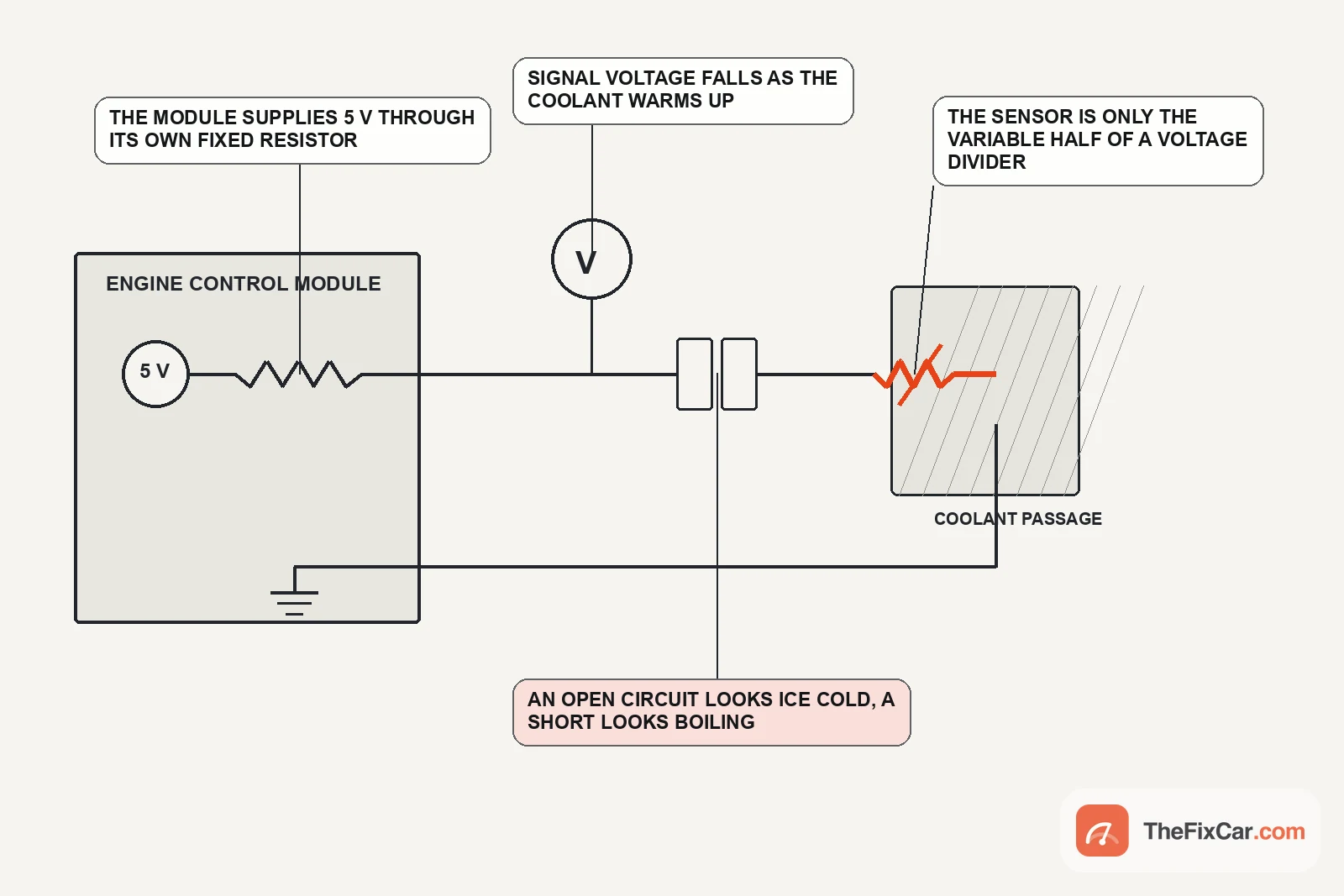
In these two-wire thermistor circuits the sensor does not work out a temperature and send it as data. On the Mitsubishi circuit cited here the ECM supplies a 5 volt feed through a resistor inside itself, the sensor pulls that line down toward ground by an amount that depends on its resistance, and the module reads the voltage left on the wire. Mitsubishi documents the arrangement down to the terminals: 5 volts leaves ECM terminal 26 through an internal resistor to sensor terminal 1, and sensor terminal 2 returns to ECM terminal 27[5]. Bosch describes the same idea from the sensor side, noting its NTC connects directly to most control units through a pull-up resistor of typically 1 or 3 kΩ[1].
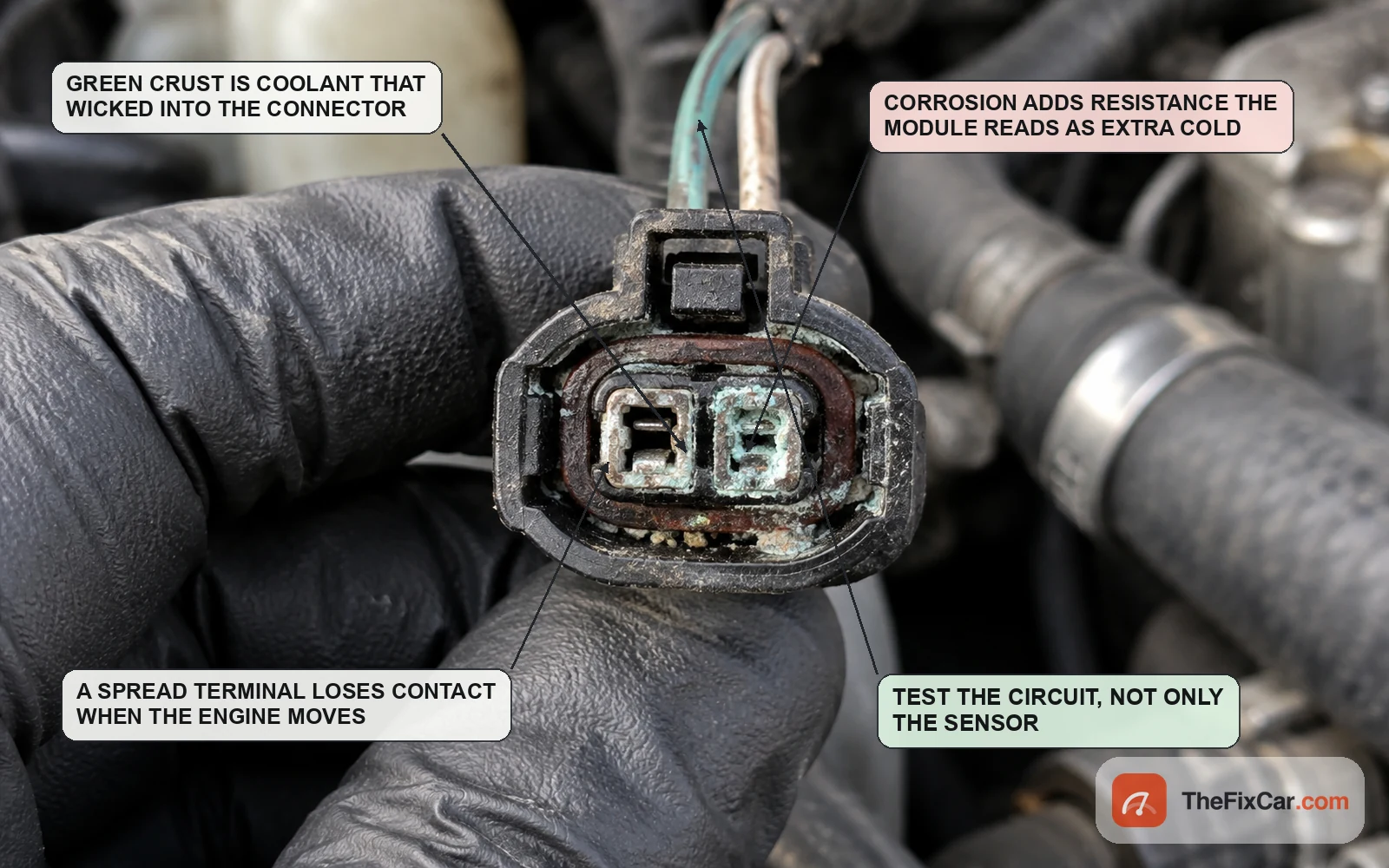
Two consequences follow in a pull-up circuit of this shape. Voltage falls as the engine warms, because falling sensor resistance pulls harder on the divider. And resistance added in series with the sensor, in a corroded terminal or a poor splice, is read as if the sensor itself were colder. A short or a leakage path to ground moves the signal the other way, which is why the direction of the error is a clue in itself.
Reading the resistance curve
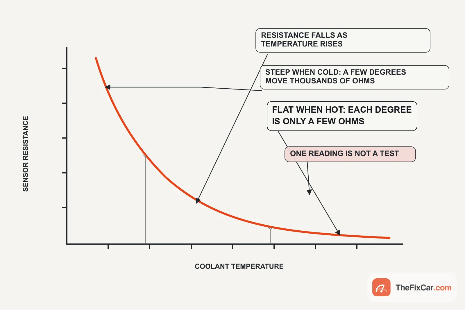
The published tables show how uneven the curve is. Between 0 °C and 20 °C the Bosch part falls from 5,896 Ω to 2,500 Ω, so that span averages about 170 Ω for every degree. Between 90 °C and 100 °C it moves from 243 Ω to 187 Ω, an average near 5.6 Ω per degree[1].
At the hot end of the curve, lead resistance matters much more during a direct resistance test. On the Bosch M12 curve, 1 Ω corresponds to roughly 0.18 °C between 90 and 100 °C, against about 0.006 °C across 0 to 20 °C. Null the meter leads before comparing a hot sensor with the published table. In the installed circuit, additional resistance at a connector produces a similar cold bias, but it does so by changing the voltage divider the ECM sees rather than by adding to a measured resistance.
Manufacturers set their own accuracy expectations against temperature as well: Bosch quotes ±1.4 °C at 25 °C and ±3.4 °C at 100 °C for the M12, and ±0.8 °C at 100 °C for the M12-H[1][2].
Normal signal voltage, and the thresholds behind P0117 and P0118
Most published coolant sensor data is resistance. One Mitsubishi service-information page gives the other half, the voltage the module should see at a given coolant temperature, measured at the sensor connector with the sensor still connected and the ignition on[11].
| Coolant temperature | Sensor output voltage |
|---|---|
| −20 °C (−4 °F) | 3.9 to 4.5 V |
| 0 °C (32 °F) | 3.2 to 3.8 V |
| 20 °C (68 °F) | 2.3 to 2.9 V |
| 40 °C (104 °F) | 1.3 to 1.9 V |
| 60 °C (140 °F) | 0.7 to 1.3 V |
| 80 °C (176 °F) | 0.3 to 0.9 V |
Mitsubishi service information, engine group 13A: voltage between sensor connector terminal 1 and ground, backprobed, ignition ON[11]. The same page specifies 4.5 to 4.9 volts as the supply at the harness-side connector. Another vehicle can divide its 5 volt feed through a different pull-up resistor and produce a different set of numbers.
Those are normal operating values. The published fault limits are a different kind of number. Mitsubishi sets the high input code when sensor output voltage stays at 4.6 volts or higher for 2 seconds, more than 2 seconds after the starting sequence completes, and lists three candidates: the sensor, an open circuit or damaged connector, and the ECM[5]. The low input code uses the mirror threshold, 0.1 volt or lower for 2 seconds, with a shorted circuit or connector damage in place of the open one[6]. A signal sitting at either limit is a circuit question before it is a sensor question: on a pull-up circuit, an unplugged connector gives the module the same high-voltage clue as an open thermistor.
What the module does with the number
California’s OBD II regulation requires that the system monitor the engine coolant temperature sensor for three separate things: circuit continuity, out-of-range values, and rationality faults[7]. Those three categories sort the ECT codes people actually see. A dead or shorted circuit is continuity. A voltage outside the design window is out of range. A reading that is electrically plausible but does not fit the operating conditions is a rationality fault, and that is the category able to catch some drifting or stuck sensors.
The rationality criterion is worth seeing written out. On one Mitsubishi application, for example, P0116 can set after a start above 60 °C when coolant temperature varies by no more than 1 °C (1.8 °F) once 330 seconds have passed and the specified acceleration and deceleration has accumulated; the same monitor uses a 3 °C (5.4 °F) criterion when the engine starts between 0 and 60 °C[8]. The reading is not out of range. It is too steady to be a real engine.
The same regulation sets the warm-up expectation that produces cold-running codes. The OBD system has to flag a thermostat malfunction if coolant does not reach a warmed-up temperature within 20 degrees Fahrenheit of the manufacturer’s nominal regulating temperature inside an approved time window, and it has to flag the ECT sensor if the engine does not reach closed-loop enable temperature within an interval that, for 2009 and later vehicles, may not exceed two minutes when the engine starts up to 15 degrees Fahrenheit below that temperature, or five minutes when it starts 15 to 35 degrees below[7]. That limit is about how fast coolant reaches the temperature the strategy needs, so the code points at the warm-up system as a whole: thermostat operation, coolant level, the sensor circuit and the calibration all sit inside it.
Where the sensor sits, and why that moves the reading
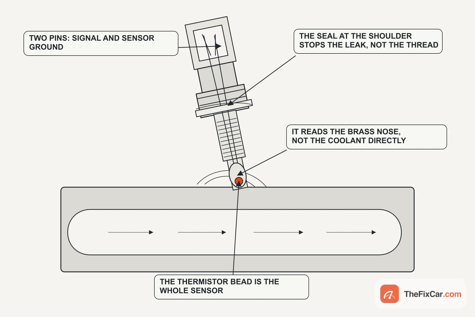
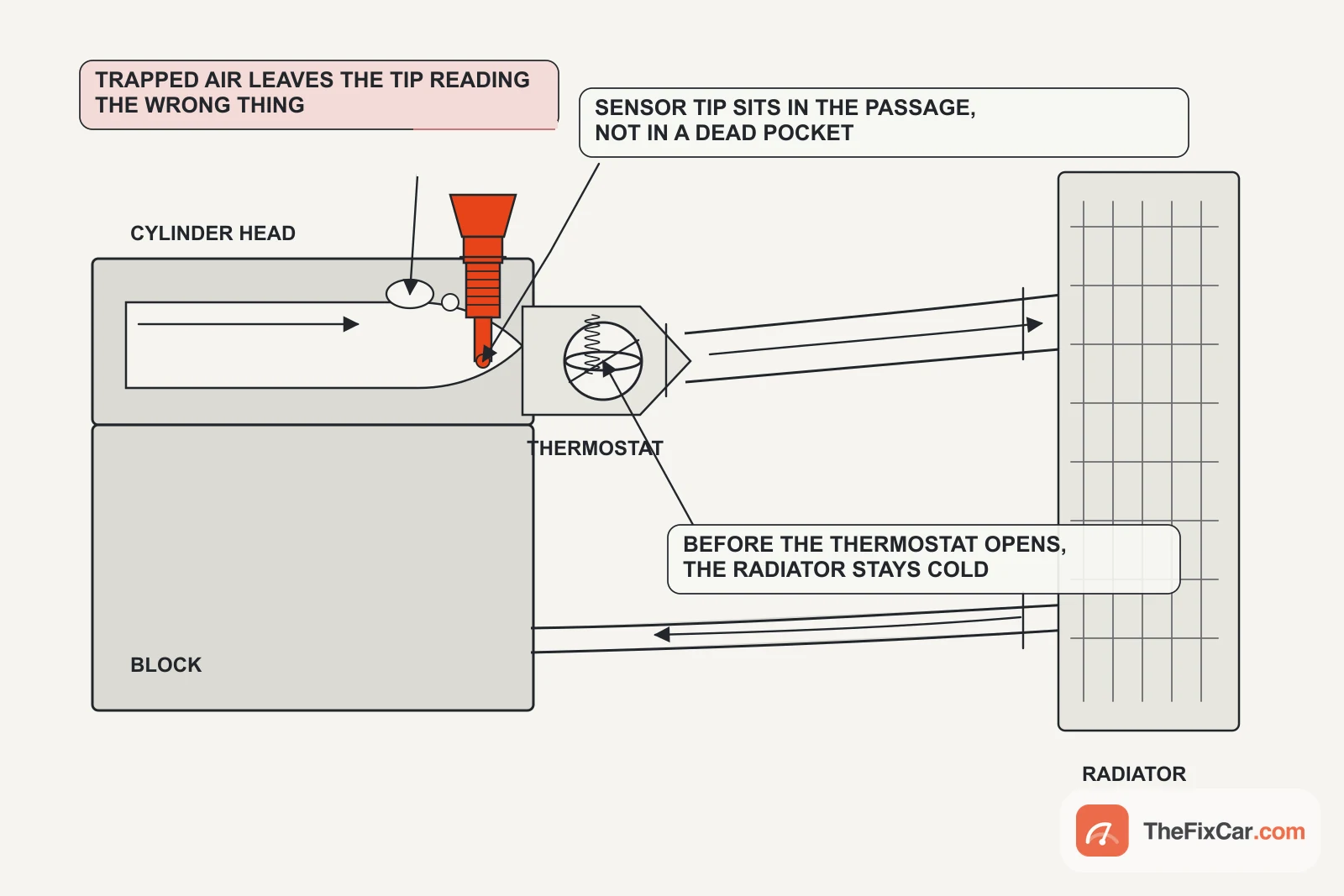
A sensor reports the temperature at its own sensing tip, not an abstract engine temperature. Whatever keeps coolant off that tip changes what the module sees, without anything electrical being wrong. Low coolant can leave the tip in vapour, and air trapped at the high point of the head after a refill can do the same. Where the sensor sits relative to the thermostat and to the flow through the head also changes what it sees, which is why published values are tied to a vehicle and a measurement point rather than to engines in general.
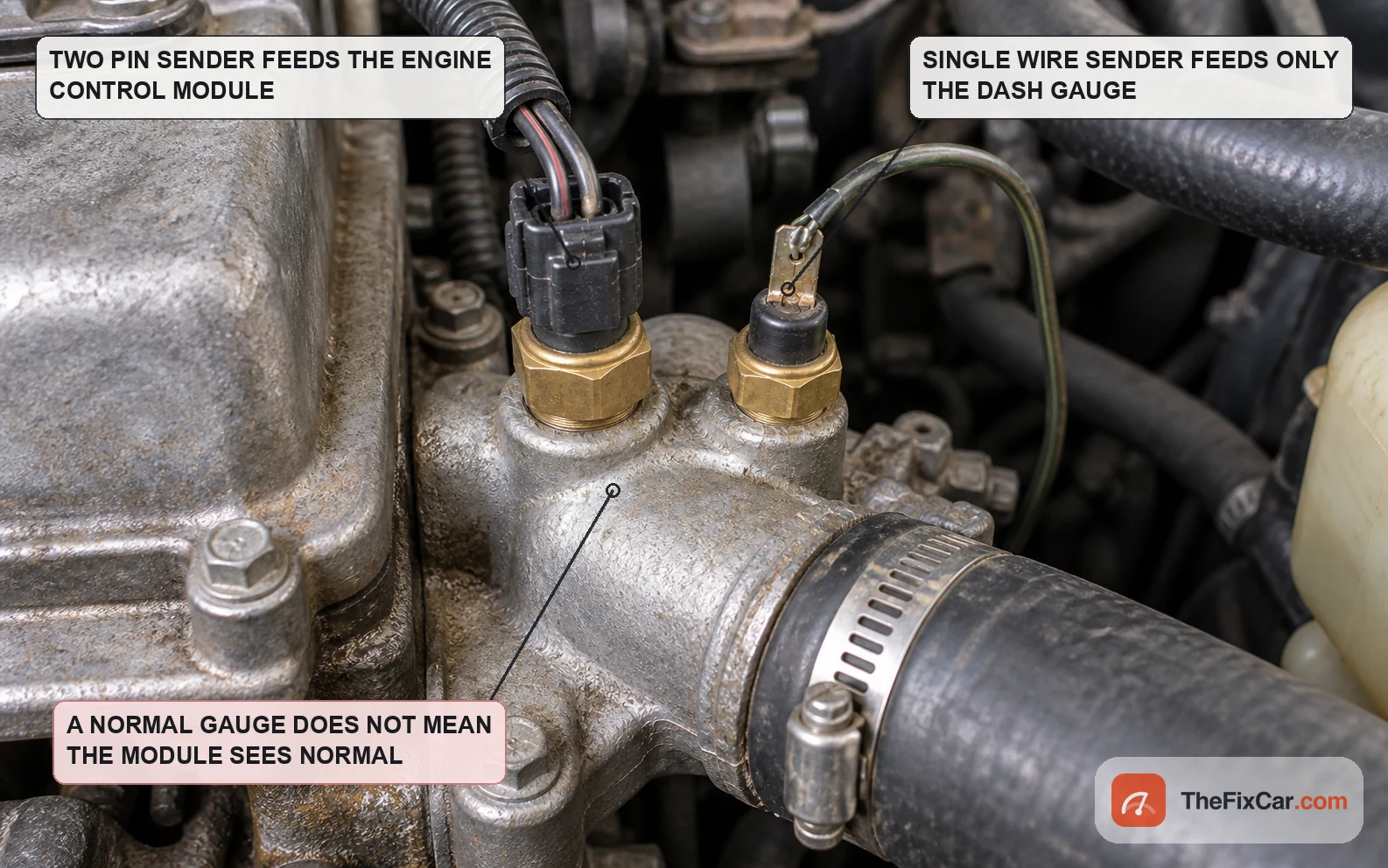
Position also explains the gap between two temperature readings on the same car. The gauge and the module do not always share a sender, and even when they do, the display may be filtered before it reaches the needle. General Motors describes both effects in a bulletin on the 2014 Corvette: the analog gauge runs a dampening program to keep the needle from moving with every fluctuation, while the digital display shows unfiltered sensor data and does not begin to read at all until coolant reaches 100 °F (38 °C)[9].
Why an in-spec sensor can still give a wrong temperature
Added resistance at the connector. Coolant that wicks into a connector corrodes terminals and adds series resistance, and because the module cannot separate sensor resistance from circuit resistance, that extra resistance reads colder than reality. Corrosion inside the sensor body does the same thing from the other side: BMW ran a service action on R55 to R58 MINI models with N16 or N18 engines built between August 2010 and March 2012 because internal corrosion could bridge the sensor’s contacts and produce an inaccurate reading[10].
Air or low coolant around the tip. A tip surrounded by vapour or trapped air no longer tracks the bulk liquid coolant, and the reading can swing as the pocket moves. Refill and bleed properly before condemning anything electrical.
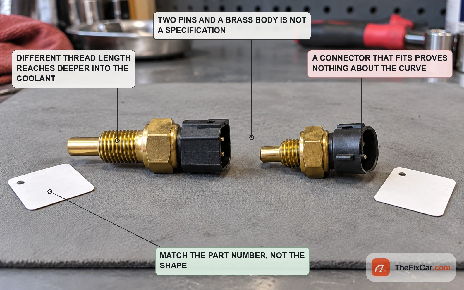
A part that fits but does not match the calibration. Thread and connector compatibility say nothing about the curve. The two Bosch catalogue parts share a resistance table but not their torque or sealing[1][2], and the Amphenol engine sensor shares neither curve nor operating range with them[3]. A sensor built to a different curve will read wrong while testing perfectly against its own table.
How to use these specifications
- Resistance. Disconnect the sensor and compare measured resistance with the value specified for your part at a known temperature. Null the meter leads first, and take the removal and heating method from your own service information.
- Signal voltage. Measure according to the wiring diagram with the sensor connected, as in the Mitsubishi table above[11]. Do not confuse a normal operating voltage with an open or short DTC threshold: 4.6 V and 0.1 V are the levels that set a code, not the levels a working sensor should sit at[5][6].
- Scan data. After a cold soak, compare the coolant reading with another credible ambient-temperature input before warm-up. A large split between two sensors that should agree is the first clue worth chasing, before anything is unplugged.
Frequently asked questions
What should a coolant temp sensor read in ohms? At around 20 °C, published examples run from 2,100 to 2,700 Ω for one Mitsubishi application[4], 2,500 Ω ±5 % for a Bosch catalogue part[1], and 10,000 Ω at 25 °C for an Amphenol engine temperature sensor[3]. Compare against the table for your part, at a measured temperature.
What voltage should the ECT signal be? On a pull-up circuit it falls as the engine warms. The Mitsubishi figures above run from 3.9 to 4.5 volts at −20 °C down to 0.3 to 0.9 volt at 80 °C, backprobed with the sensor connected[11]. Anything pinned near 4.6 or 0.1 volt is a circuit question first[5][6].
Can I test a coolant temperature sensor without removing it? Partly. Scan data and a backprobed signal voltage while the engine warms will show whether the value moves smoothly and whether the circuit is open or shorted. The Mitsubishi resistance check takes the sensor out and immerses the sensing tip at a known temperature[4], so follow the procedure written for your vehicle before anything is unscrewed.
Is the coolant temperature sensor the same as the temperature sender for the gauge? Not always. Some vehicles use separate parts, and a shared signal may still be processed before it reaches the dial. The GM bulletin cited here is one worked example, with a damping program and a display threshold[9].
Does a P0128 or cold-running code mean the sensor is bad? Not on its own. The regulation ties that family of codes to how quickly coolant reaches temperature, and the thermostat criterion sits in the same section[7].
Sources & verification
Last technically reviewed: Sep 2026
Reviewed by: Marcus Holt, Senior Diagnostic Technician
Primary references: sensor manufacturer data sheets, OEM service information pages, manufacturer service bulletins filed with NHTSA, California Air Resources Board OBD II regulation
Suggested citation: TheFixCar, “Engine Coolant Temperature Sensor Specs: Resistance, Voltage and Test Values,” updated Sep 2026. https://thefixcar.com/specs/engine-coolant-temperature-sensor-specs/