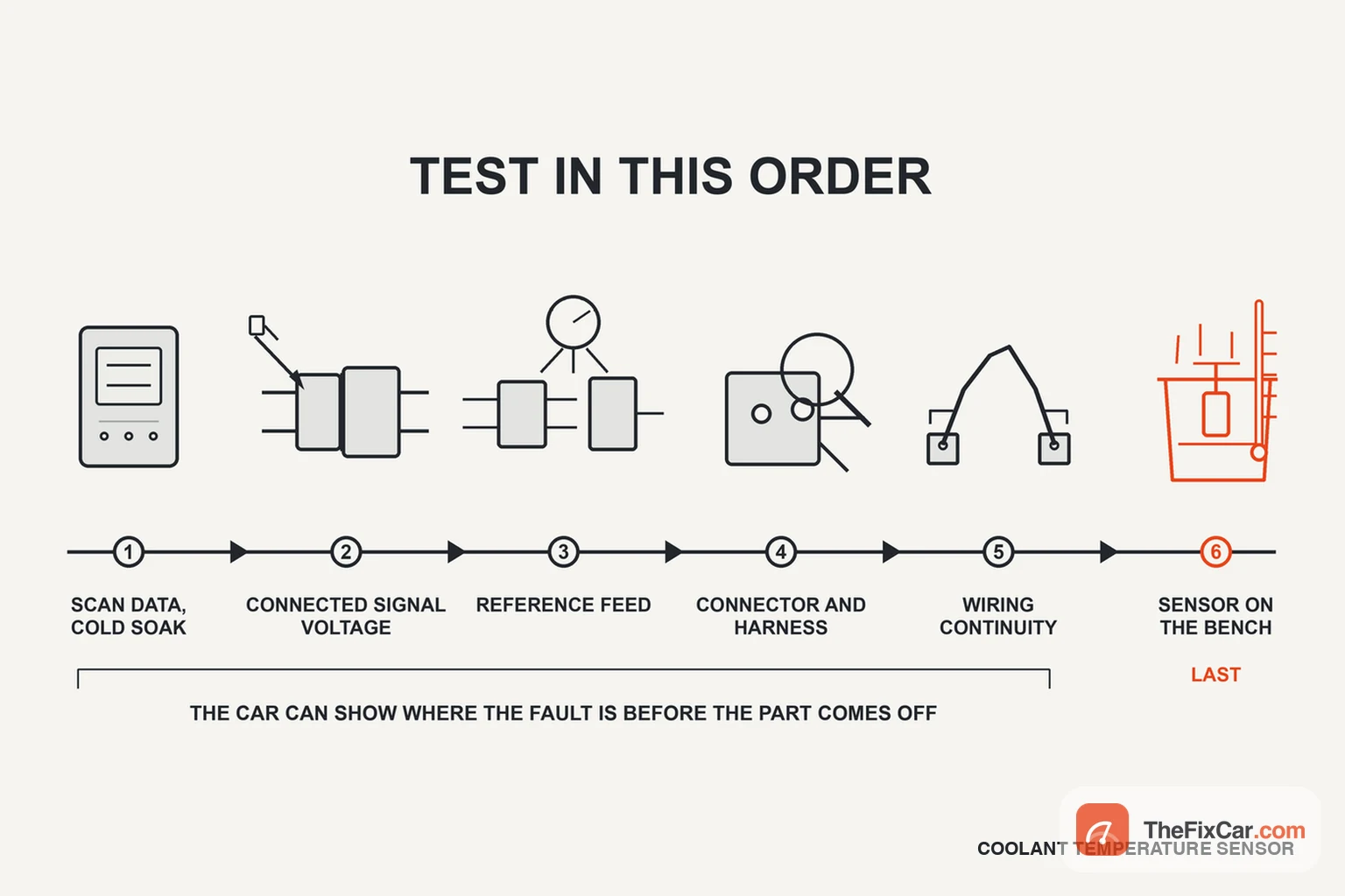

A coolant temperature sensor can pass a resistance test and still produce a wrong reading once it is connected to the car. Corroded terminals, resistance in the wiring and leakage inside the connector all change the voltage the module actually sees.
So test in that order: scan data first, connected signal voltage second, the connector and wiring next, and the sensor itself last. The procedure below follows that order and explains what each test can and cannot tell you.
Quick answer
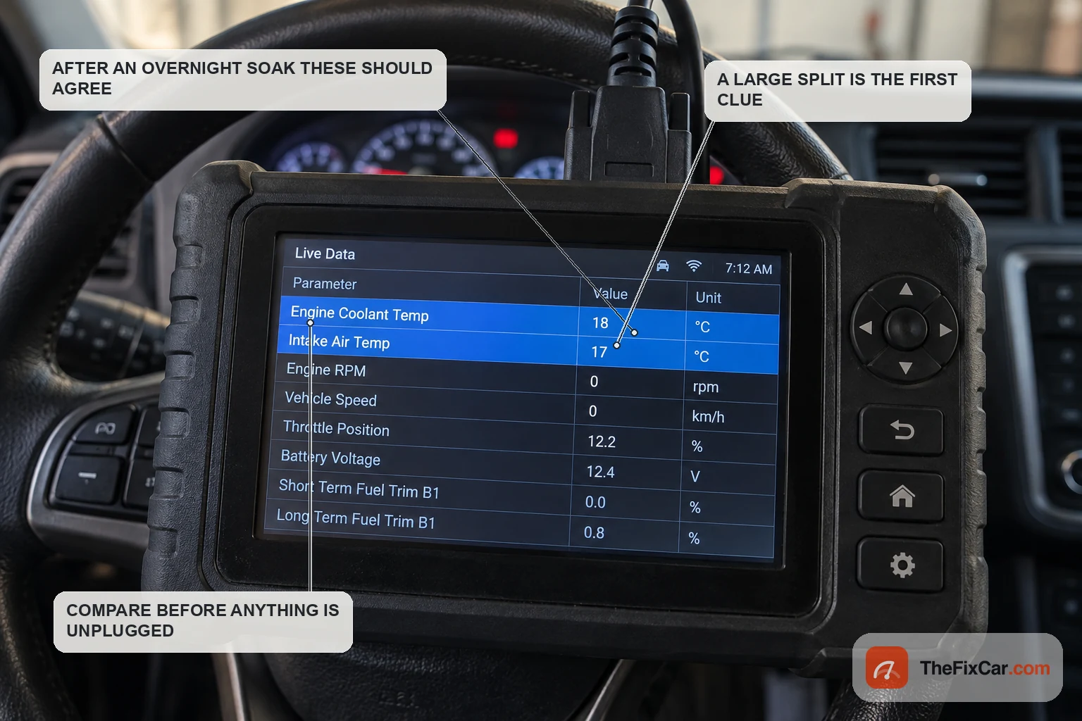
Start with the engine cold and a scan tool, not a wrench: compare coolant temperature against intake air temperature after an overnight soak, since coolant, engine metal and intake air should all be near the same ambient temperature by then. Next, backprobe the signal wire with the sensor still connected and watch the voltage fall as the engine warms. The bench resistance check comes last, because it is the only step that cannot see the wiring. Budget 20 to 40 minutes for the testing and, on an accessible sensor, another 30 to 60 minutes for the replacement and refill.
The one thing not to skip: do not open a hot cooling system. Hot coolant is pressurised, and it can flash into steam as that pressure is released. Let the engine cool completely before the system is opened or the sensor is disturbed.
What each test actually proves
| Test | What it tells you | What it does NOT prove |
|---|---|---|
| Cold-soak scan data, coolant against intake air | Whether the reported temperature is believable before the engine starts | Which of the two sensors is wrong when they disagree, and anything at all about accuracy once the engine is hot |
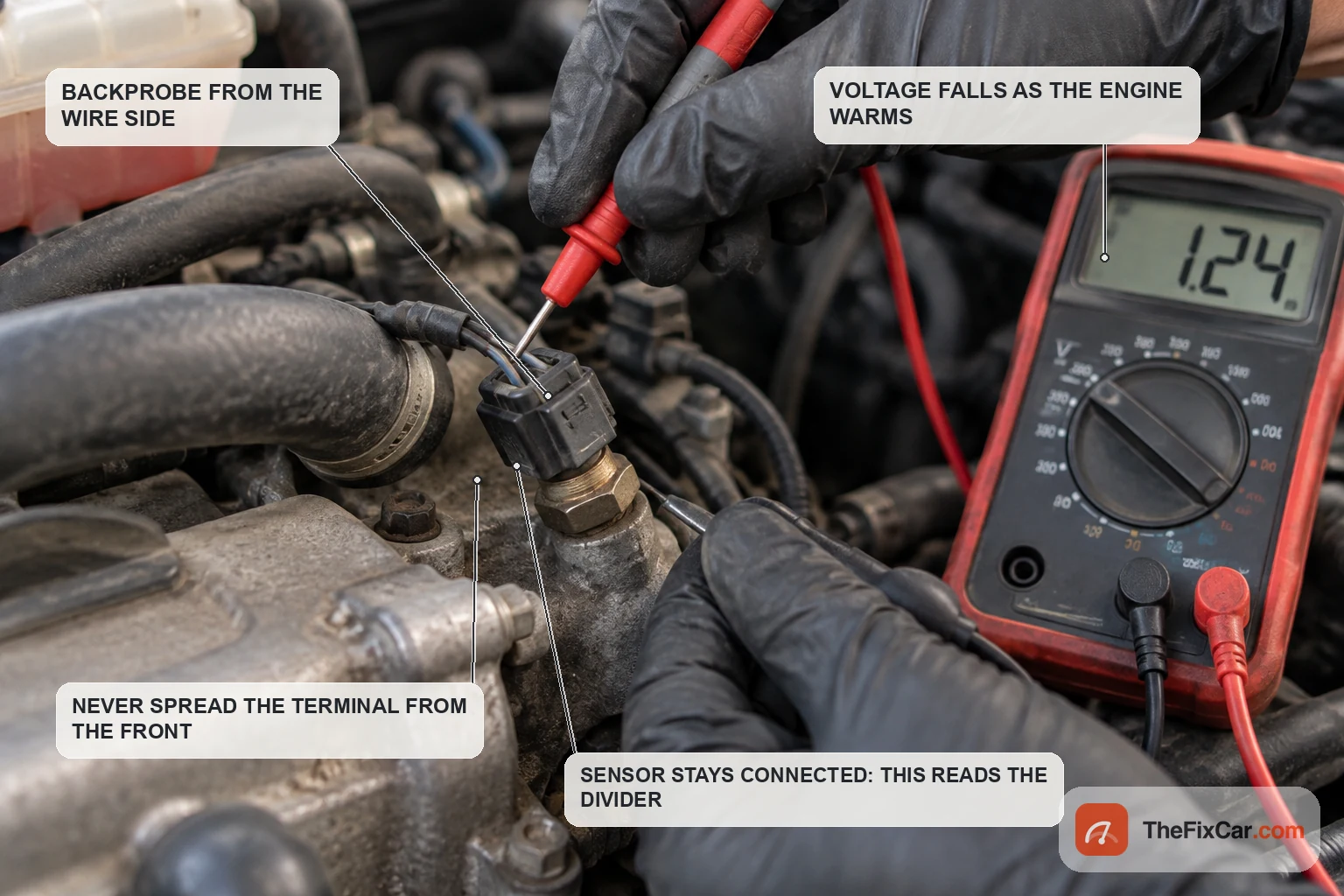
| Connected signal voltage, backprobed while the engine warms | Whether the sensor and its wiring behave correctly together, as one divider | Which half of that divider is at fault when the value is wrong |
| Reference feed at the harness-side connector, sensor unplugged | Whether the module’s feed reaches the connector at all | Anything about the sensor, the ground return, or resistance that only shows up under load |
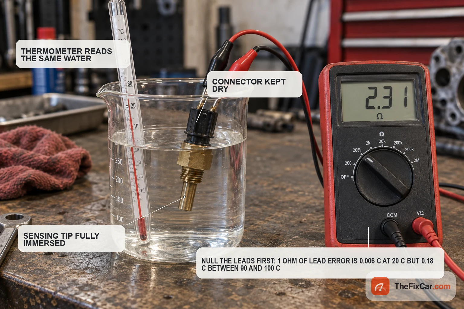
| Two-temperature resistance test, sensor removed | Whether the thermistor follows its published curve at two known points | Response time, behaviour between and beyond those points, and everything about the circuit it was plugged into |
Why the circuit comes before the part
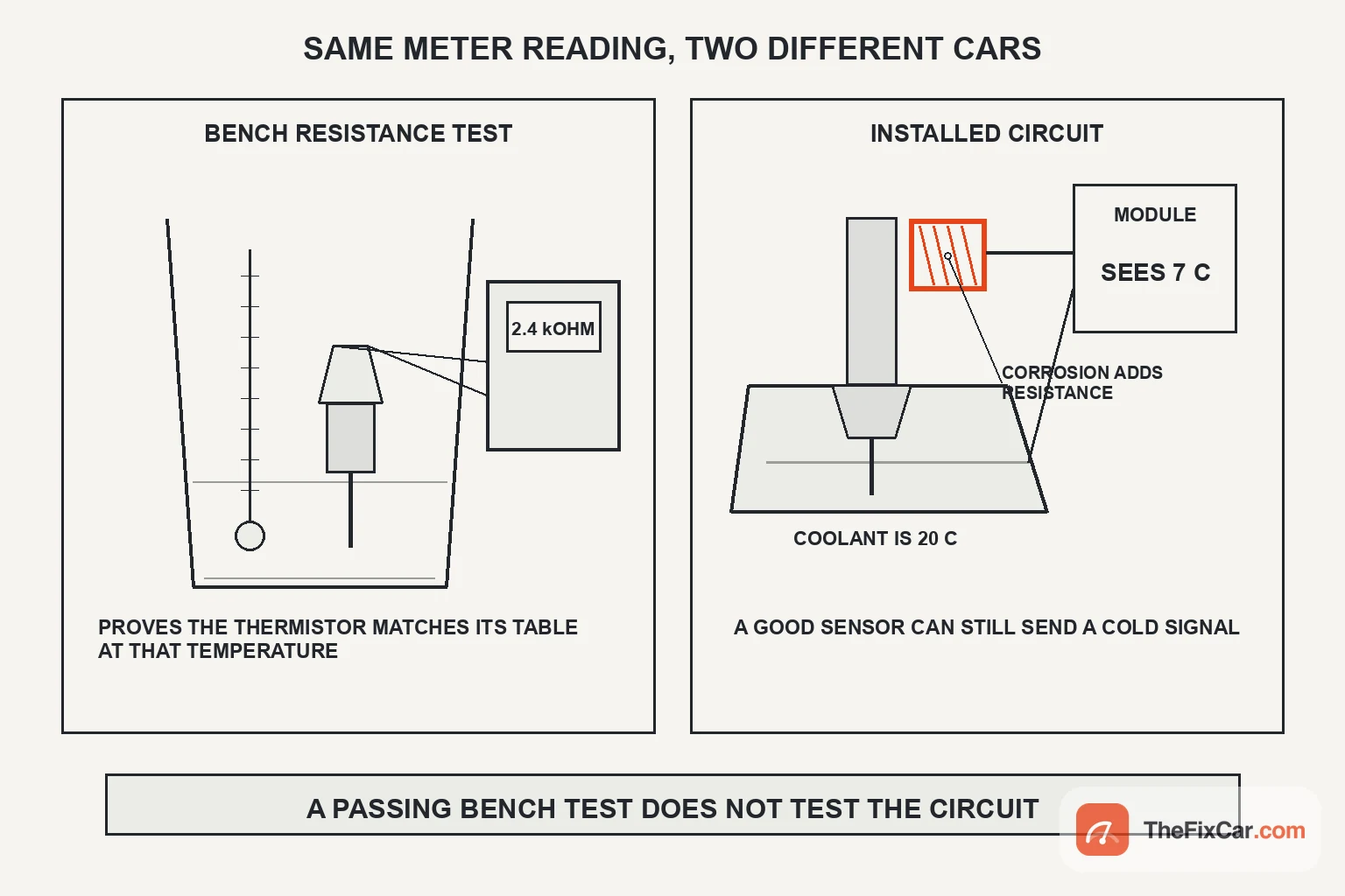
The module reads the voltage the sensor and its wiring create together, not the sensor’s resistance on its own. Added series resistance can make that circuit look colder than the coolant really is, while leakage toward ground can make it look hotter. That is why a sensor can pass on the bench and still produce the wrong scan-data temperature once it is installed.
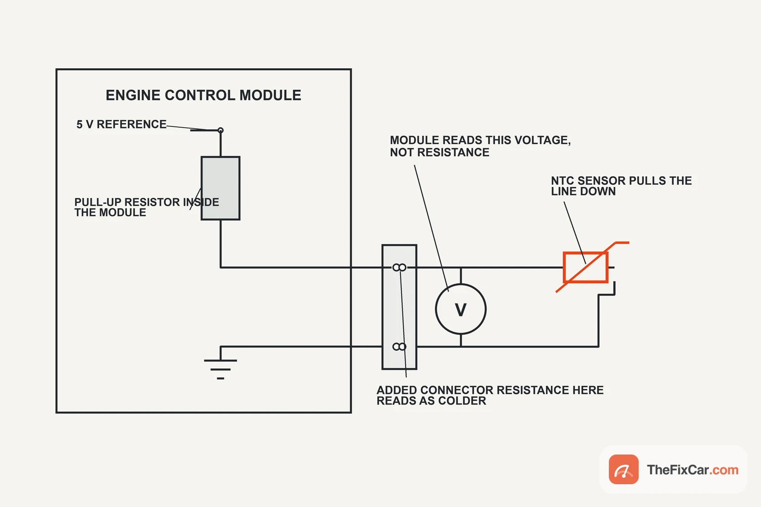
Mitsubishi documents one such circuit terminal by terminal: 5 volts leaves the ECM through an internal resistor to the sensor, and the sensor’s second terminal returns to a separate ECM pin[3]. The direction of the voltage error helps separate added resistance from a leakage path, which is another reason to test the circuit while it is still connected.
When to start testing
- A coolant temperature circuit code. Mitsubishi sets its high input code at 4.6 volts or higher held for 2 seconds and the low input code at 0.1 volt or lower for the same interval[3][4]. That manufacturer’s own cause list names the wiring, the connector and the ECM alongside the sensor, so the code narrows the circuit rather than naming the part.
- A rationality code. These flag a reading that stays electrically plausible but does not behave the way the monitor expects[5], which covers some stuck and slow-changing inputs.
- An implausible cold-soak value. Coolant and intake air temperature that disagree after a night parked put one of the two readings in doubt.
- A reading that freezes or jumps during warm-up. A value that climbs in steps, sticks at one number, or drops back while the engine is heating points at the circuit or the sensor rather than at the cooling system.
Before you unplug anything
- Do not open a hot cooling system. Wait until the engine is cold, not merely warm.
- Do not condemn the sensor on a code alone. A circuit code covers the sensor, the wiring, the connector and the module.
- Do not probe a sealed connector from the front. Spreading a female terminal creates the exact fault you are hunting. Backprobe from the wire side, or use a breakout lead if the service information provides one.
- Do not pierce wire insulation. A pierced strand under a boot becomes a corrosion site months later.
- Do not assume the replacement matches. Thread and connector compatibility say nothing about the curve, the torque or the sealing method[6][7].
How to test it
Work down this order and stop when a step points somewhere specific.
- Read the cold-soak data first. After an overnight soak, compare coolant temperature and intake air temperature on a scan tool. They should sit close together. A wide split tells you one of them is wrong without telling you which, which is what the next step is for.
- Backprobe the connected signal while the engine warms. With the sensor still plugged in, backprobe the signal wire from the wire side and watch the voltage fall as coolant temperature rises. On the Mitsubishi circuit cited here that means roughly 2.3 to 2.9 volts at 20 °C falling to 0.3 to 0.9 volt at 80 °C[2]. Exact voltage, resistance and torque figures vary by application: our engine coolant temperature sensor specs page carries the documented reference values by part number. Route the leads and keep your hands clear of belts, the fan and the exhaust before it runs.
- Only if the signal is wrong, unplug and check the feed. With the sensor disconnected and the ignition on, measure at the harness-side connector. The Mitsubishi procedure cited here expects 4.5 to 4.9 volts there[2]. A missing or low reading sends you to the circuit rather than the part, but confirm the terminal identification and your ground reference first: measuring the wrong pin looks identical to a dead feed.
- Inspect the connector as carefully as the sensor. Green or white crust on the terminals, a spread female terminal, or coolant residue inside the housing all change what the module reads. Corrosion in series reads colder, a leakage path between terminals biases the signal the other way. Wiggle the connector and the harness near it while watching live data, since an intermittent fault shows up under movement and not on a static reading.
- Check the wiring between the two ends. With the ignition off and the module connector released as the service information directs, check continuity from each sensor terminal to its module pin, and check each wire against ground for a short.
- Bench-test the sensor at two temperatures. With the sensor out, immerse the sensing portion and compare resistance against the published values for that part at each temperature[1]. Short the meter probes together first and subtract any lead resistance, especially when checking the sensor hot, where its resistance is low enough for the leads to matter. Stir the water and read the thermometer and the meter at the same moment. One point can agree by luck; two points describe a curve.
How to replace it
The steps below are the shape of the job. Torque figures, sealant type, drain points and the bleed procedure come from the service information for your vehicle, because they differ between parts on the same engine family.
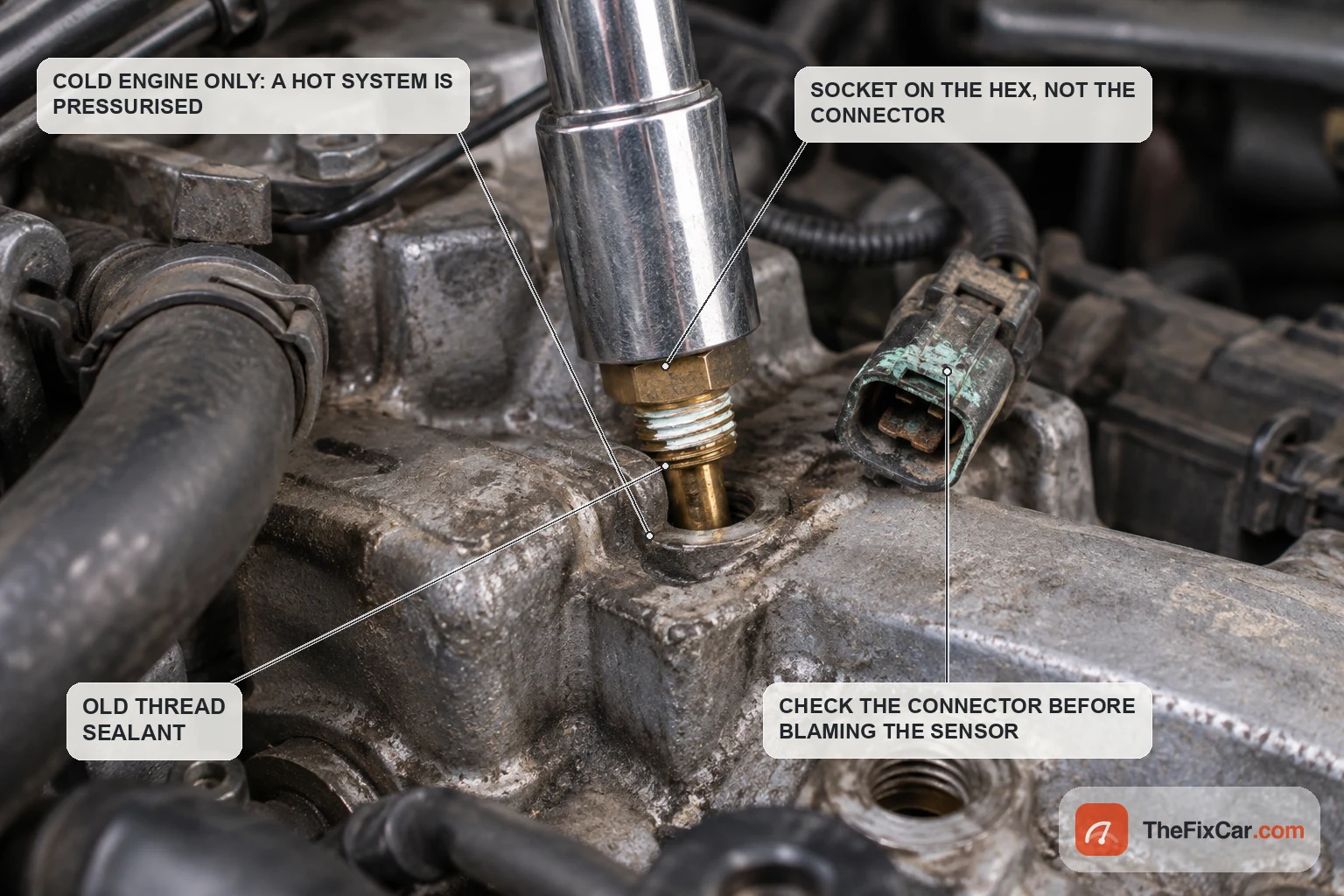
- Start cold. No exceptions on a sealed cooling system.
- Drain to below the sensor. The Mitsubishi procedure drains the coolant before the sensor comes out[1]. How far down depends on where the sensor sits. Catch what comes out, keep it off belts and pulleys, and refill only with the coolant type and mix specified for the vehicle.
- Disconnect the battery if the procedure calls for it, then release the connector by its lock tab. Find the tab before pulling, and support the harness rather than the connector body.
- Use the right tool on the hex. Mitsubishi specifies a dedicated sensor wrench positioned so the tool never touches the connector body[1]. A deep socket that clears the terminals does the same job where no special tool is specified.
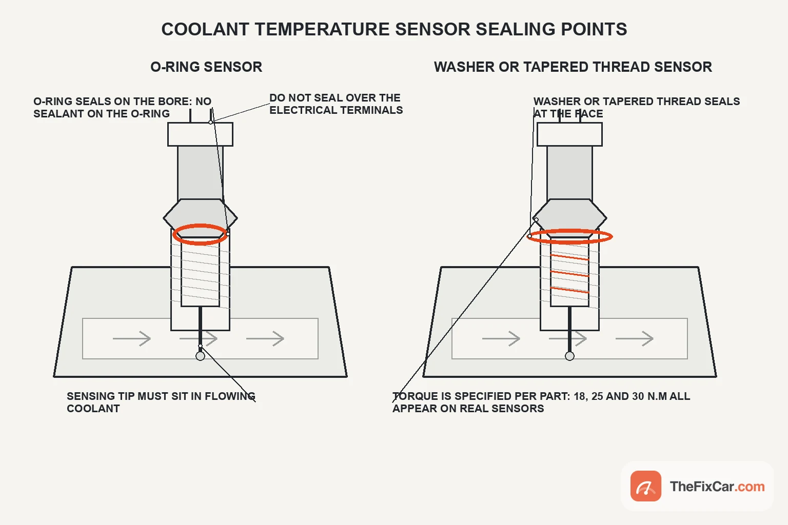
- Compare old and new before fitting, and seal it the way the part is designed to seal. Thread pitch, reach, hex size, connector keying, the sealing method and the resistance curve all have to match. Two sensors that thread into the same hole can carry different torque figures and different sealing, one on a supplied washer and one on thread sealant[6][7]. Sealant on a part designed to seal on an O-ring is a leak waiting to happen, and a crush washer is not reused.
- Torque to the published figure for that part. The specified values differ between parts, so take yours from your own service information rather than from another sensor that looks the same.
- Refill, bleed, then verify with data rather than the gauge. Air trapped around the sensing tip can isolate it from circulating coolant and distort the reading, so follow the bleed procedure for your vehicle. Then let the engine reach operating temperature, watch the scan value climb smoothly, check for leaks at pressure, and confirm no new codes have set.
DIY difficulty and tools
- DIY difficulty: moderate for the diagnosis, easy to moderate for the replacement depending on access. The testing above wants a scan tool, backprobing on a running engine and continuity checks at the module connector. The replacement itself can be straightforward on an exposed sensor and a much larger job on one buried beneath an intake assembly, sometimes with most of the coolant out.
- Tools: a multimeter, backprobe pins, a scan tool that shows live data, a thermometer and a container of water for the bench check, a torque wrench, and the correct sensor socket or the specified special tool.
- Parts: buy by application rather than by picture, and budget for coolant to refill whatever comes out.
Frequently asked questions
Can I test a coolant temperature sensor without removing it? Yes. Scan data and connected signal voltage are the better first tests anyway, and resistance can also be checked with the sensor disconnected but still fitted, as long as you know its temperature. Taking it out is mainly what makes a controlled two-point water test possible.
What should the sensor read on the meter? Whatever the specification for that exact sensor or vehicle application requires, at the temperature you measured.
Do I have to drain the coolant to change it? Usually some of it. How much depends on where the sensor sits relative to the coolant level, and the procedure for your vehicle says how far to drain. The Mitsubishi procedure cited here drains before removal[1].
My new sensor reads wrong. What did I miss? Three things are worth checking before the new part is blamed: air trapped around the tip after the refill, a part with a different resistance curve, and a connector that was already corroded before the sensor was changed.
Is thread sealant always needed? No. It depends on how the part seals: some are supplied with a sealing washer, others specify a named thread sealant[7][1]. Use what the service information for your part calls for.
Does a cold-running code mean the sensor is bad? Not on its own. The regulation ties those codes to how quickly coolant reaches the required temperature, and the thermostat criterion sits in the same section[8].