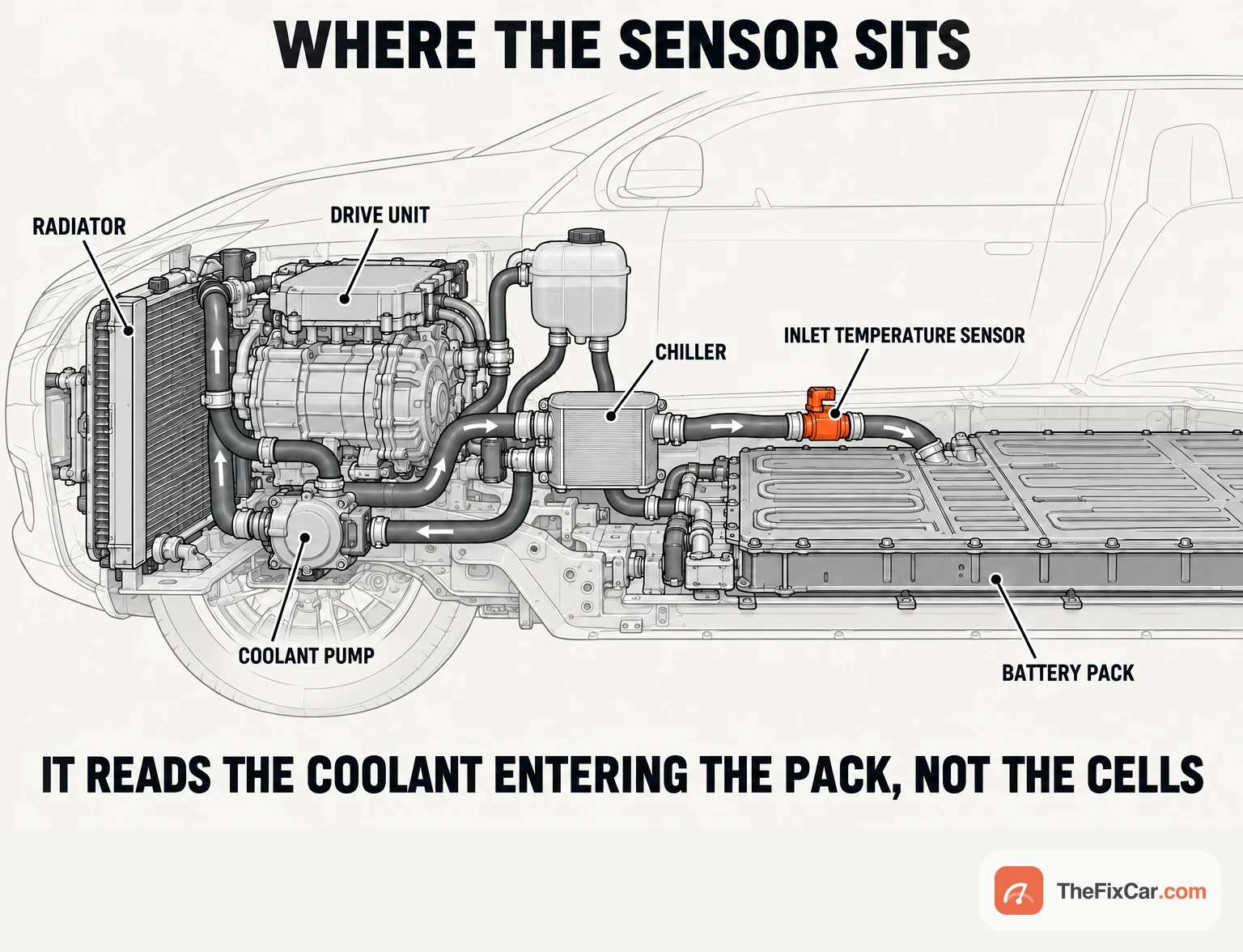
An EV coolant temperature sensor measures coolant temperature at its installation point in a battery or electric-drive thermal circuit. Circuit layouts vary: the battery, the inverter, the motor and, on a plug-in hybrid, the combustion engine may sit on separate or interconnected coolant circuits. The thermal controller uses the reading alongside other inputs when it decides how to run the pump, the chiller and the heater.
The sensor documented in this guide, Mitsubishi’s EV coolant temperature sensor in its 2023 plug-in hybrid service information, is a two-wire NTC thermistor. Its diagnostic chart, and the Tesla Model Y hose procedures used as the second example, set the order of everything below.
Quick answer
Start with the scan tool, not the multimeter. Read the stored codes, then the EV coolant temperature in live data under the soak and operating conditions the carmaker specifies, and compare it with the temperature readings the carmaker’s own plausibility check uses. A reading that is electrically implausible, or that disagrees with its comparison sensors by more than the permitted difference, moves the diagnosis to the circuit and only then to the sensor. How much of the job is plumbing depends on where the sensor sits: the documented Mitsubishi sensor mounts on the power drive unit, and the cited power drive unit removal procedure requires draining the EV coolant loop, and on the 2020 to 2024 Tesla Model Y it rides on a coolant hose at the front of the car. Before the circuit is opened, follow the exact vehicle’s requirements for electrical isolation, cooling-system cooling, refilling and bleeding.
What each test can and cannot tell you
| Test | What it tells you | What it does NOT prove |
|---|---|---|
| Scan data under the OEM’s soak and operating conditions, compared with the carmaker’s reference sensors | Whether the reading is plausible against the comparison the controller itself makes | Which sensor is wrong when two disagree, and anything about accuracy outside the conditions tested |
| Connected signal voltage, back-probed where the OEM procedure permits it | The signal voltage at that measurement point under the conditions tested | Whether the sensor is accurate across its range, whether a fault is intermittent, or which part of the sensor, wiring, reference supply or module input is responsible for a wrong value |
| Signal and ground wire checks from the OEM procedure, sensor unplugged, circuit de-energised | Whether the circuit passes the particular visual and electrical checks that procedure specifies | Intermittent faults, insulation damage that has not yet produced an electrical fault, and voltage drop under conditions not tested |
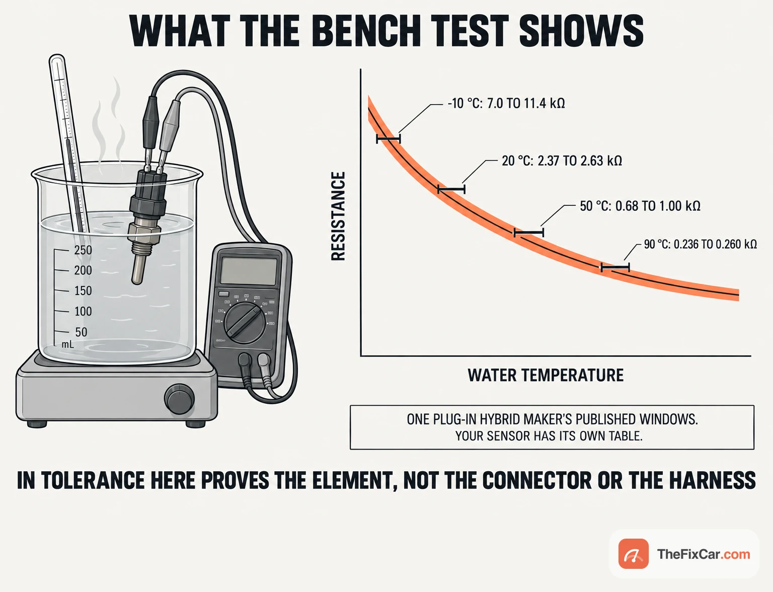
| Hot-water resistance test with the sensor removed | Whether the thermistor sits inside its published window at the temperatures you tested | Response time, behaviour between the tested points, and everything about the connector and harness it came out of |
Why the circuit comes before the part
In a conventional two-wire NTC pull-up circuit, the module feeds the sensor through a pull-up resistor from an internal reference and reads the voltage at the junction. A cold thermistor has high resistance and holds the junction near the reference; a hot one pulls it toward ground. Mitsubishi’s PHEV-ECU data list, item 660, shows voltage falling as temperature rises, running from about 4 V at 0 °C through 3.5 V at 20 °C and 2.7 V at 40 °C to 1.9 V at 60 °C, each with the electric motor switch in power-on mode.[2] In this pull-up circuit, resistance added in the sensor’s signal or return path, a corroded terminal or a damaged strand, raises the voltage at the module input and makes the coolant look colder than it is. An open sensor path pulls that input toward the reference; a signal-wire short to ground pulls it low. A measurement at the sensor connector can differ from what the module sees if the harness between them has a voltage drop, and scan data may show a substituted value once the module has detected a fault. The divider arithmetic and the engine-side voltage tables are on the engine coolant temperature sensor specs page; use the Mitsubishi EV sensor’s own voltage table when interpreting its readings.
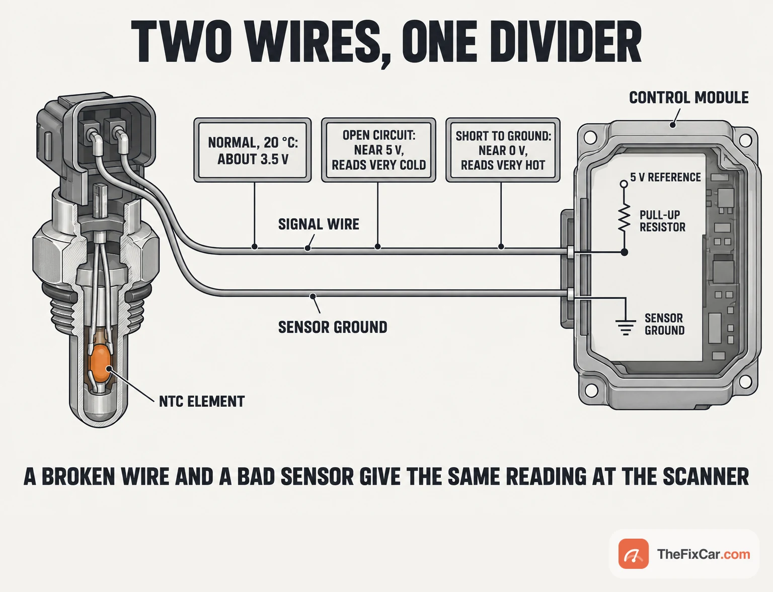
That is also why the carmaker’s own procedure puts the wiring before the sensor. Mitsubishi’s P0A01-00 chart checks for power drive unit codes first, then the data list value, then the signal line (terminal WTS) and the ground line (terminal WTSG) between the sensor connector and the PHEV-ECU connector for damage, an open, a short to ground and a short to power, and only then sends the technician to the sensor inspection. The code itself is a range/performance check: it sets when the EV coolant temperature and the power drive unit’s IGBT temperature differ by more than 31 °C for 1,700 seconds after a soak of more than 2,700 seconds, with the listed causes being the sensor, its circuit and the PHEV-ECU.[2] A passing bench test does not rule out a connector fault.
Where the sensor sits on an EV
There is no single location, and the location decides how much of the job is plumbing. The cited 2020 to 2024 Model Y supermanifold procedure identifies two hose-mounted coolant temperature sensors, one on the chiller-to-battery hose and one on the powertrain supply hose, with connections near the coolant bottle. The harness with purple tape goes to the sensor closest to the coolant bottle.[6][8] Tesla services the chiller-side sensor through the hose procedure: on the left-hand-drive dual-motor Model Y the procedure unlocks and disconnects the sensor connector and removes the chiller-to-battery hose as one assembly.[6]
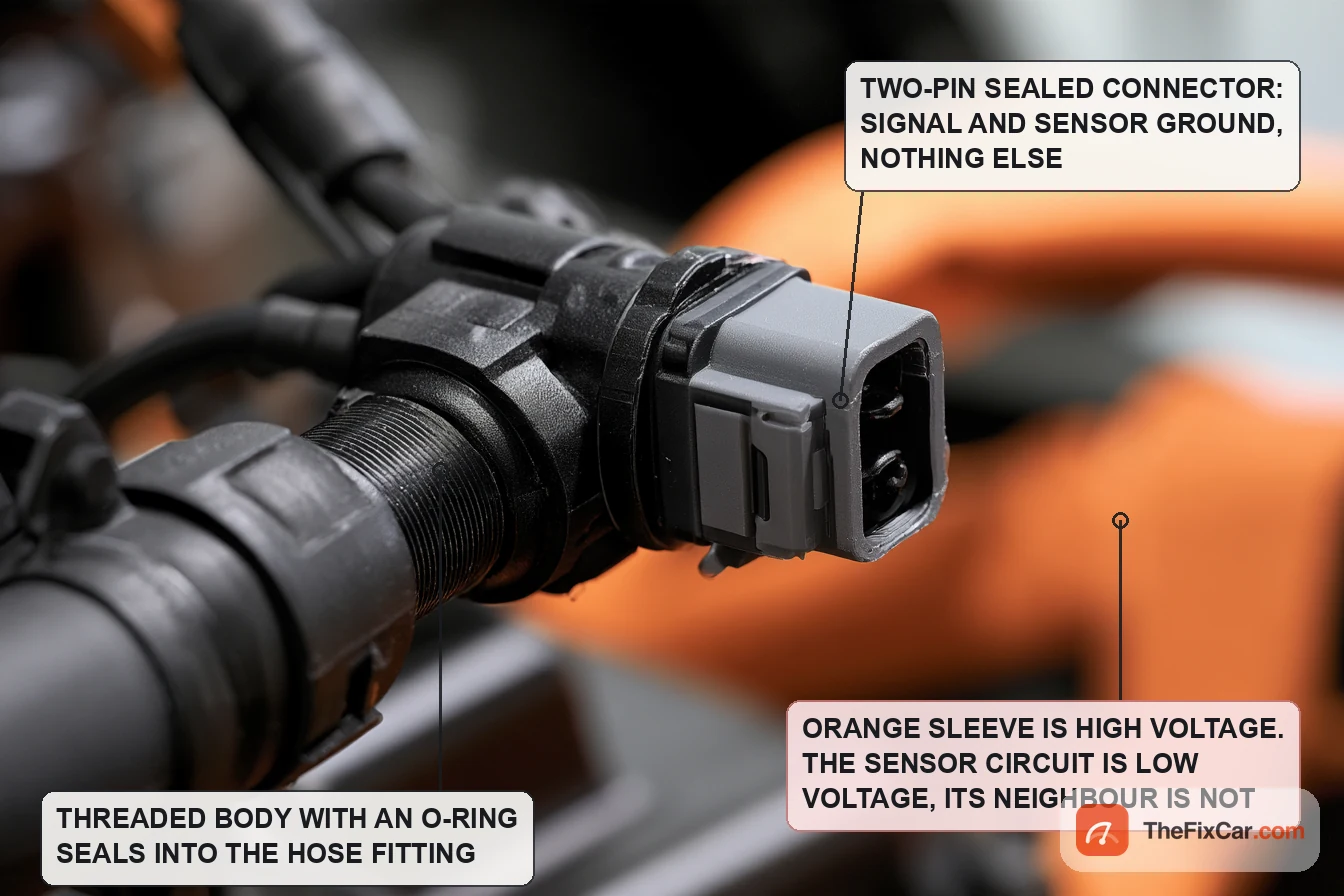
Mitsubishi’s 2023 plug-in hybrid service information puts its EV coolant temperature sensor on the power drive unit, sealed with an O-ring. The power drive unit removal and installation page lists the sensor harness connection among the early disconnections and the sensor and its O-ring among the removal items, with EV coolant draining required before the work starts; the pages do not name the model, so the applicable sensor-replacement procedure for the exact vehicle sets the access and removal sequence.[3]
Amphenol’s WTF083B001 is one manufacturer-documented example of an NTC sensor intended for EV and PHEV battery coolant: 2,828 Ω at 25 °C, with an operating range of −40 °C to 100 °C.[9] Temperature range, resistance curve, connector, seal and thread are application-specific, so the replacement is the part approved for the vehicle, not a sensor that happens to fit the thread.
How to test it
- Read and record fault codes first. The Mitsubishi diagnostic sequence checks for power drive unit codes before it proceeds with P0A01-00, because the comparison that sets the code uses the drive unit’s IGBT temperature.[2] Write down freeze-frame data before erasing anything.
- Read the sensor in live data under the specified conditions. Compare the EV coolant temperature with the carmaker’s comparison sensors under the OEM’s soak and operating conditions. Charging or thermal conditioning can keep temperatures from equalising while the car is parked, so a long park does not by itself make the readings comparable. On the Mitsubishi data list, item 660 should read about 3.5 V at 20 °C with the electric motor switch in power-on mode.[2] A value near a signal-voltage limit can indicate a circuit fault; interpret it with the vehicle’s own specifications and procedure.
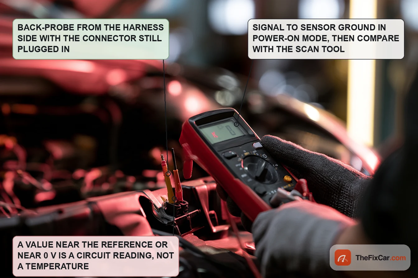
- Back-probe the connected sensor where the procedure permits it. Use the specified pins, the specified vehicle state and fine probes or a breakout adapter; do not force probes into sealed terminals. The sensor circuit is low voltage, but if reaching its connector means working inside a high-voltage service area, the test belongs to someone trained for that area, under the carmaker’s safety procedure. Compare the meter reading with the OEM’s raw-voltage data item under the same conditions; a temperature PID needs the right voltage-to-temperature relationship behind it. Agreement does not isolate the sensor from the harness, and disagreement can come from measurement points, voltage drop, scan-data processing or the module’s input circuitry. Continue with the OEM fault-isolation procedure.
- Check the two wires with the circuit de-energised. Follow the OEM wiring-test procedure, including its power-down requirements and connector-disconnection steps, and isolate module connections where it says to. Mitsubishi’s chart checks the signal line and then the ground line between the sensor connector and the PHEV-ECU connector for damage, an open, a short to ground and a short to power, and sends you to repair the connector or harness when either fails.[2] Check each wire against the wiring diagram’s expected connections and inspect terminal condition and tension; continuity to ground on the return wire is not itself evidence of a fault where the wiring diagram specifies that connection, but it does not prove the return circuit is sound either. Flex the accessible low-voltage harness while measuring if the procedure allows it, because a strand that opens only when the loom moves will not show on a static test.
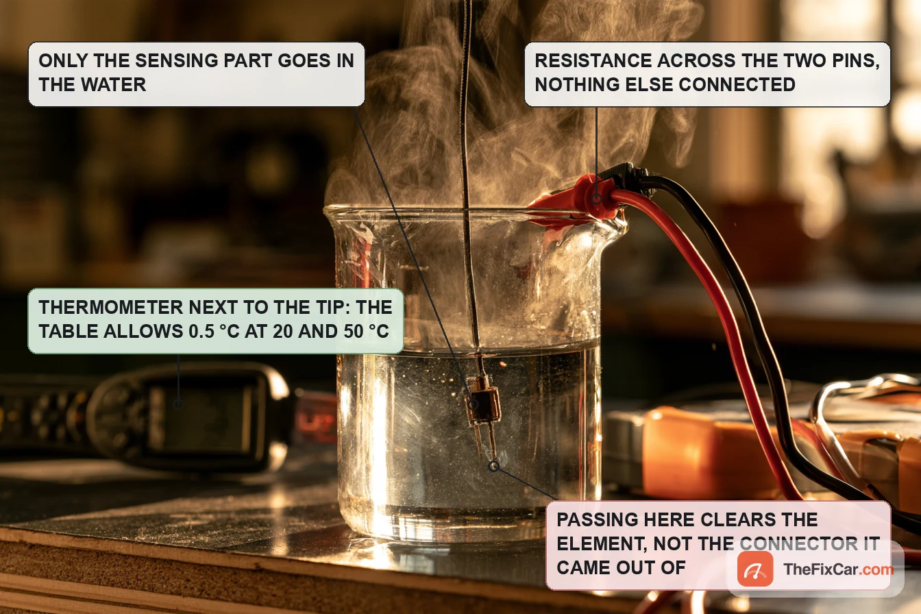
- Bench-test the sensor last, if the procedure allows removal. Mitsubishi’s inspection immerses the sensing part in hot water and measures resistance between the two terminals, with windows of 2.37 to 2.63 kΩ at 20 °C and 0.68 to 1.00 kΩ at 50 °C among the published points; a reading outside its window means replacement.[1] The published water-temperature tolerance is ±0.5 °C at the 20 °C and 50 °C points. Control and measure the bath within that tolerance, and allow for thermometer uncertainty and bath stability when judging a borderline reading. Keep the connector dry, let the sensor and the bath stabilise before reading, and leave the sub-zero and above-boiling points in the table to equipment that can reach them. Confirm the part identity, the temperature and the setup before condemning an out-of-range sensor.
- Confirm the repair the way the carmaker does. Mitsubishi closes its chart with the OBD-II drive cycle and a recheck of the code.[2] An absent code before the monitor has run is inconclusive. If the code returns, go back through the chart and verify its prerequisite inputs and circuit checks before considering the PHEV-ECU, which the chart lists only after those checks pass.
For an engine coolant sensor, see the guide on testing and replacing an engine coolant temperature sensor.
How to replace it
Two documented examples follow. Each is a summary of the OEM procedure, not a substitute for it. Hot coolant is pressurised and can flash into steam as pressure is released; let the loop cool completely before a cap or a drain plug comes off.
Mitsubishi plug-in hybrid: sensor on the power drive unit
From the 2023 plug-in hybrid service information; the pages name the PHEV system, not the model.
- Isolate the high-voltage system. High-voltage isolation is required on this application before the power drive unit is touched: Mitsubishi’s precautions page sets waiting periods, 12 V disconnection, service plug removal in insulating gloves and a residual-voltage check with a high-voltage multimeter.[5] Follow that complete procedure and leave the step to trained personnel if that is not you.
- Drain the EV coolant loop. Remove the front under covers, then the drain plug and the EV radiator condenser tank, and collect the coolant. The documented quantity is 4.7 dm³ (5.0 quarts); the drain plug goes back with a new O-ring at 1.2 ± 0.4 N·m.[4]
- Remove the sensor and fit the new one with a new O-ring. Release the connector lock first; the power drive unit page lists the sensor and its O-ring as the last two removal items, so the sensor-replacement instructions for the exact vehicle set the access.[3] Use the tightening value in the service information, reconnect the harness and engage the lock.
- Restore the service plug and the 12 V supply at the stage the procedure prescribes; the refill and bleed both need the car in power-on or READY mode.
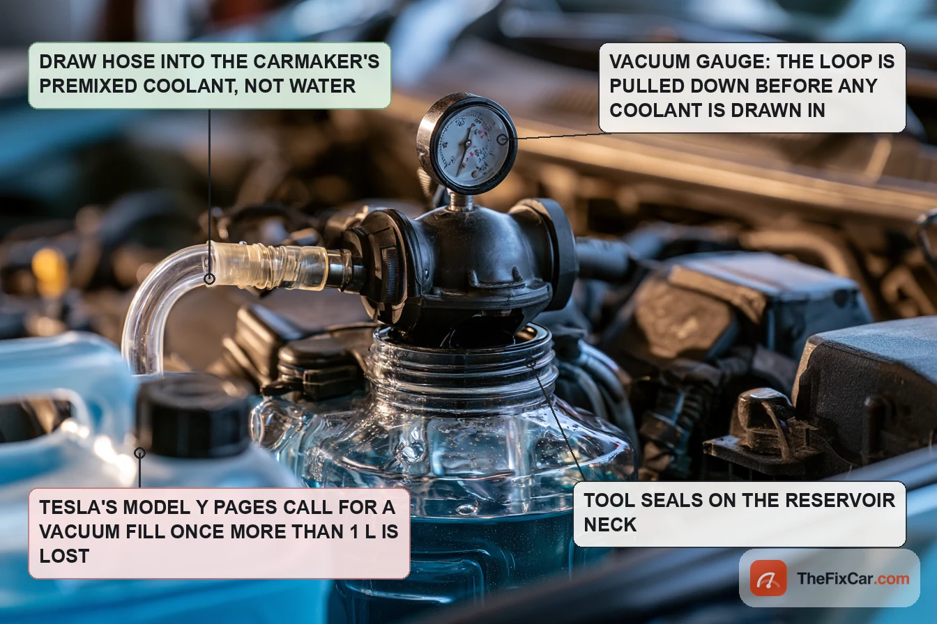
- Refill with the specified coolant. Mitsubishi specifies its Super Long Life Coolant Premium or an equivalent, premixed at 50 % and used without adding water. Fill to the condenser tank filler port, then run the EV coolant refilling control (a M.U.T.-III special function, or a switch sequence described in the procedure) and keep topping up for the 3 to 4 minutes the pump cycles until the level stops falling.[4]
- Bleed the air and check the level. Run the electric water pump for at least 1 minute in READY mode or through the actuator test, and treat the bleed as complete when the condenser tank stays at the MIN line or above after the pump stops. Do not run the pump with the level below MIN; doing so can damage the pump bearing. Then set the final level to the specified mark, and erase DTC P3126-01 if air in the pump set it during the refill.[4]
Tesla Model Y: sensor serviced with the coolant hose assembly
The 2020 to 2024 Model Y manual replaces the chiller-to-battery hose with its sensor as one assembly; the configuration each step comes from is named.
- Start the thermal fill-and-drain routine in Service Mode before any hose is opened, with drain containers under the car (left-hand-drive dual-motor procedure).[6]
- Disconnect the sensor and remove the hose. Release the connector lock, disconnect the hose at the supermanifold and the battery manifold, plug the open fittings and remove the hose with its sensor.[6]
- Install the new hose assembly and perform a push-pull-push test on each quick-connect fitting to prove it is seated. Reconnect the sensor and engage the lock; the purple-taped harness goes to the sensor nearest the coolant bottle.[6]
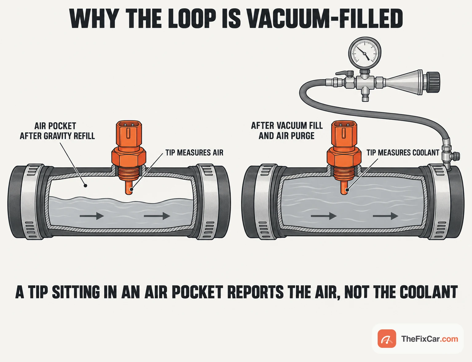
- Vacuum-refill, purge, check the level. The left-hand-drive dual-motor procedure vacuum-refills, stops the routine, runs the coolant air purge and tops off the level.[6] The right-hand-drive rear-wheel-drive procedure for the same hose states that coolant loss greater than 1 L requires vacuum fill and finishes at the Max line.[7]
Air pockets can impair circulation and make a coolant temperature reading unrepresentative, and both the Mitsubishi coolant-change procedure and the Tesla hose procedures include a bleeding or purging step. Complete the vehicle’s filling and bleeding procedure before judging the repair, and use the coolant specification and concentration the exact vehicle requires without diluting a product supplied ready-mixed. Why the specification on the bottle matters more than its colour applies here as much as on an engine loop.
Prove the repair. Check for leaks and the coolant level, confirm the sensor reads plausibly, then run the confirmation drive cycle and verify the monitor completed with no code.[2] Do not road-test a car with unresolved coolant loss, overheating or a stop warning.
DIY difficulty and tools
Reading codes and live data suits an owner with a scan tool that shows the carmaker’s data items rather than generic PIDs. Electrical testing needs the wiring diagram for the two sensor wires, the approved access method, a multimeter with fine back-probes or a breakout adapter, and the OEM diagnostic procedure. A bench test that needs the sensor out also needs the draining, isolation and refill work that goes with it. Any task that involves high-voltage isolation or a high-voltage service area needs appropriate training and the vehicle-specific equipment and procedure.[5] The refill and purge need the equipment specified for the vehicle, which may include both a vacuum fill tool and an OEM software routine, plus drain containers and the specified coolant.[4][7] A workshop bill covers diagnosis, the specified sensor or hose assembly, access labour, coolant, and the refill and bleeding work.
Frequently asked questions
Where is the coolant temperature sensor located on an EV?
It depends on the car. The cited 2020 to 2024 Model Y supermanifold procedure identifies sensors on the chiller-to-battery and powertrain supply hoses near the coolant bottle.[8] Mitsubishi’s 2023 plug-in hybrid mounts its EV coolant temperature sensor on the power drive unit.[3] Use model-specific service information to locate the sensor.
How do you reset an EV coolant temperature sensor?
The passive NTC sensing elements discussed here have no reset function. After the repair, follow the vehicle’s procedure for clearing faults and confirming the repair, including any required monitor or drive cycle.[2] On the Mitsubishi, a P3126-01 set by air in the pump during refilling is erased once the bleed is complete.[4]
What does Mitsubishi’s P0A01-00 code tell you?
P0A01-00 identifies an EV coolant temperature range/performance fault, not a failed sensor. In the cited Mitsubishi application the controller compares the EV coolant temperature with the power drive unit’s IGBT temperature under specified conditions, and the listed causes are the sensor, its circuit and the PHEV-ECU.[2] Other carmakers use their own codes and criteria.
Is it the same part as an engine coolant temperature sensor?
The cited sensors use NTC thermistors, but the sensing principle alone does not establish part compatibility. Temperature range, resistance curve, connector, seal and thread are set per application, and the Amphenol battery coolant sensor above is specified for −40 °C to 100 °C where Mitsubishi’s inspection table for its EV sensor runs to 150 °C.[1][9] Confirm the approved replacement through OEM part information.
Can you keep driving with the code set?
The code alone does not establish whether driving is safe or whether the signal has been lost. Follow the vehicle’s warning messages and the OEM instructions. If there is overheating, significant coolant loss or a stop warning, stop safely and arrange recovery, and do not continue driving or charging until the fault has been assessed. Have an unexplained temperature fault diagnosed promptly.
Can the coolant temperature sensor stop the EV from charging?
Potentially, depending on the vehicle’s control strategy, but the Mitsubishi source used here does not establish that consequence.[2]