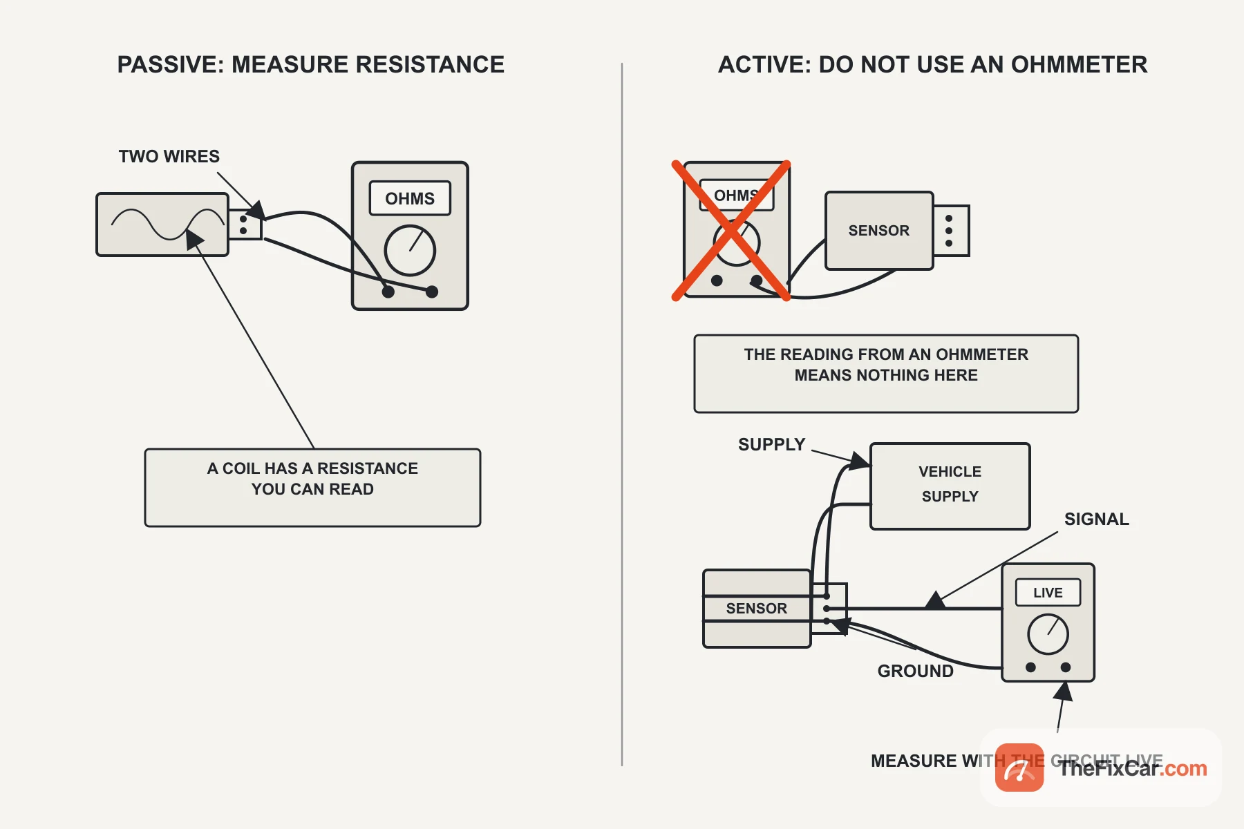
Put an ohmmeter across an ABS wheel speed sensor and you will get a number. On a car with an active sensor that number usually tells you nothing, because there is no winding for it to measure. Some manufacturers do define an electrical check for their own active sensors, so the rule is to use the test your service information gives rather than the one your meter offers.
That is the first thing to settle, because every specification below depends on it. A passive sensor generates its own voltage and can be measured with a meter in your hand. An active sensor needs power. Many two-wire versions signal by switching current, while three-wire Hall sensors commonly use a separate voltage output.[5] Either way an ohmmeter reading is not a universal health check, and on some designs the manufacturer warns that a resistance test can damage the sensor.[5] They do the same job and can share a connector count, but they need different tests.
Quick answer
A passive wheel speed sensor is a coil, so it has a real resistance and a real AC output. Bendix specifies 1200 to 2700 ohms across the pins on its WS-24 sensor, with a minimum output of 0.25 volts AC when the wheel is turned by hand at half a revolution per second.[1] An active sensor generally has no meaningful coil resistance specification. Use the powered-circuit test defined for that vehicle: the MV-1 bulletin, for one, has the technician feed the sensor from the battery through a fused jumper and read 4 to 8 mA low and 11 to 16 mA high while the wheel turns slowly.[3] In the two-wire current-interface design, the published example below switches its supply current between 7 mA and 14 mA, and the module reads that switching as a square wave.[4] An open circuit reading from an active sensor tells you nothing about the sensor, because the meter is not testing anything the sensor does.
Verified specifications at a glance
| Specification | Value | Application named in the document | Source |
|---|---|---|---|
| Passive sensor resistance | 1200 to 2700 Ω | Bendix WS-24 wheel speed sensor, commercial vehicle air brake systems | [1] |
| Measurement temperature window | 0 to 100 °F (-18 to 38 °C) | Same checklist, wheel end must not be hot | [1] |
| Passive sensor output | 0.25 V AC minimum | Wheel turned by hand at half a revolution per second, measured at the ECU | [1] |
| Chassis harness wire resistance, end to end | Less than 5 Ω | Chassis harness on the vehicles that bulletin covers, which names Bendix and Wabco sensors | [2] |
| Circuit isolation to ground | Greater than 100 kΩ | Same harness test | [2] |
| Harness resistance, sensor to module | Less than 2 Ω | 2011 to 2014 MV-1 | [3] |
| Active sensor current, low state | 4 to 8 mA | 2011 to 2014 MV-1, measured while spinning the wheel slowly | [3] |
| Active sensor current, high state | 11 to 16 mA | Same test, same vehicles | [3] |
| Active sensor output current, low | 7 mA nominal, 5.6 to 8.4 mA tolerance band | KMI15 magnetoresistive sensor module | [4] |
| Active sensor output current, high | 14 mA nominal, 11.2 mA minimum | Same module | [4] |
| Those currents as voltage | 0.81 V low, 1.61 V high across a 115 Ω series resistor | Manufacturer reference circuit | [4] |
What these numbers do NOT mean
They are not a range you can apply to your car. The 1200 to 2700 ohm window belongs to one Bendix sensor family on commercial vehicles with air brakes, and the checklist that contains it starts by telling you to drain the air system.[1] Figures published for other sensors differ. Look yours up rather than borrowing this one.
A resistance inside the window does not mean the sensor works. It means the winding is not open or shorted at rest. The same document goes on to a voltage test precisely because a coil can measure perfectly and still produce too little output once the air gap, the tone ring or the sensor face is wrong.[1]
And the 7 to 14 mA figures are a component specification from a sensor manufacturer, not a value your scan tool will display.[4] They tell you what the waveform should look like on a scope with a current clamp or across a known resistor. They do not tell you what a specific vehicle’s module expects.
Passive or active: the split that decides every test
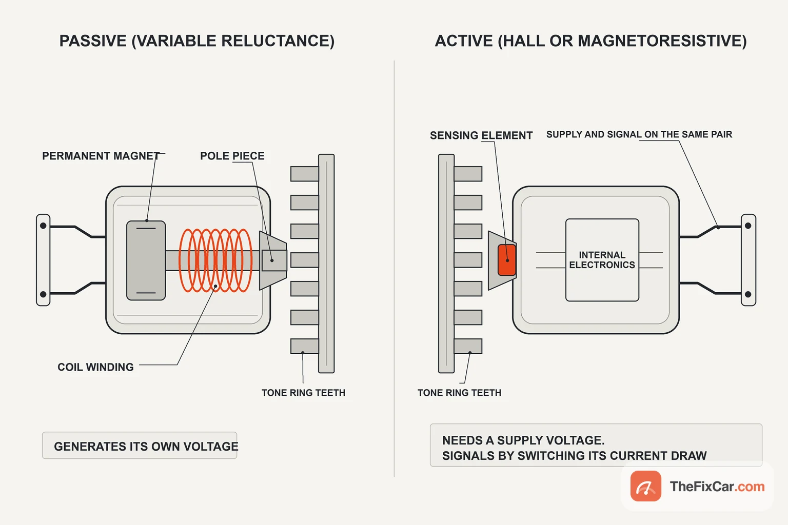
A passive sensor is a generator. A magnet, a coil and a pole piece sitting in front of a toothed ring. Teeth passing the pole change the magnetic flux, the coil produces an alternating voltage, and both the amplitude and the frequency of that voltage rise with wheel speed. Nothing powers it. That is why you can read its resistance with the car switched off, and why its output shrinks as the wheel slows until the module can no longer use it.
An active sensor is a powered circuit. It is fed a supply through the module circuit, and a Hall or magnetoresistive element inside switches the current draw between two levels as the ring passes. Amplitude no longer carries speed information. On the simplest interface the frequency does, and richer protocols also encode direction and status in the same current pulses. The payoff is that the signal keeps its size as the wheel slows, and the manufacturer states that a magnetoresistive element can measure rotation down to zero speed.[4] Reading a wheel that is barely turning is where a passive sensor runs out, because its output falls away with speed.
Two wires is not a reliable way to tell them apart. Plenty of active sensors use two, drawing power and signalling on the same pair.
How passive sensor specifications are measured
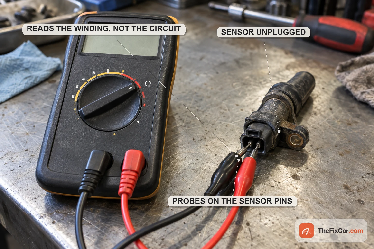
Resistance first, because it is quick and it catches an open or shorted winding. Disconnect the sensor so you are not measuring through the module, then read across its own pins. Bendix wants 1200 to 2700 ohms on the WS-24, and calls anything outside that a replacement.[1]
Temperature is part of the specification, not a detail. The same checklist requires the vehicle to be at 0 to 100 °F, which is -18 to 38 °C, and warns that the wheel end must not be hot.[1] Copper resistance climbs with temperature, so a reading taken after a drive can put a healthy sensor out of range.
The output figure has its own conditions. The 0.25 volts AC minimum is quoted with the wheel turned by hand at least half a revolution per second and the meter at the module end, so the harness is inside the measurement.[1] Reaching that condition means getting the wheel off the ground safely, which is a job for rated stands on level ground rather than a jack.
Reading an active sensor, and why the ohmmeter lies
There is no winding to read. What the meter sees is the input of a semiconductor, and what it reports depends on the meter’s own test current as much as on the part. A low reading, a very high one and an open circuit can all come from the same working sensor, which is why the number cannot be compared against anything.
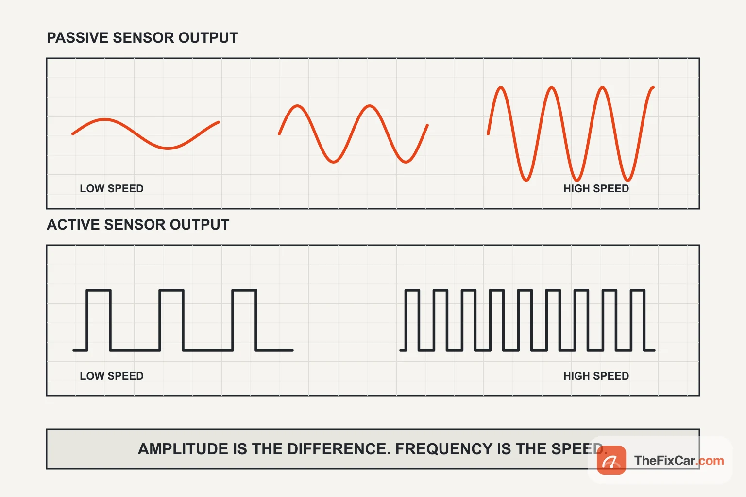
On a scope, the guided test for a Hall effect sensor shows a clean square wave whose frequency tracks wheel speed.[5] The real test needs the circuit alive, and it needs the method your service information specifies rather than an improvised one. Where that method is a current measurement, the sensor runs on its normal supply and the switching is read with a current clamp or across a known resistor. On the KMI15 family the low state is 7 mA nominal with a 5.6 to 8.4 mA tolerance band and the high state is 14 mA nominal with an 11.2 mA minimum, which across the manufacturer’s own 115 ohm resistor becomes about 0.81 volts and 1.61 volts.[4] You are looking for a clean two-level switch that sits inside whatever band your service information gives. The levels above belong to that sensor family and are an illustration of the shape, not a target for another vehicle.
Air gap and tone ring
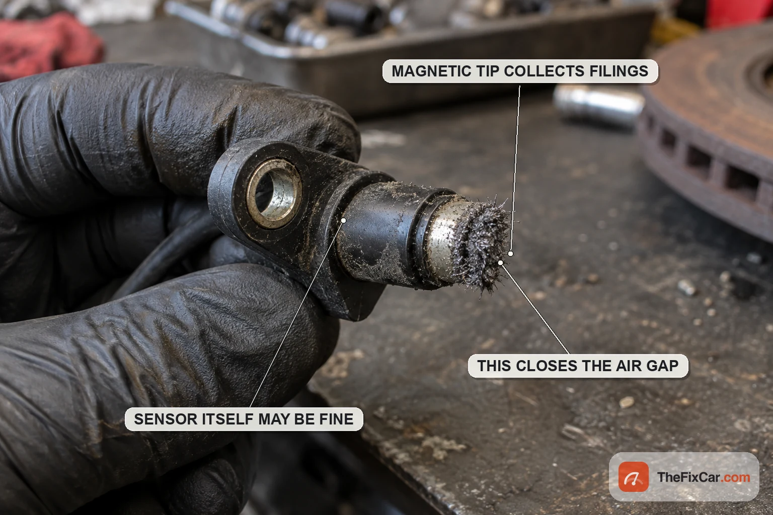
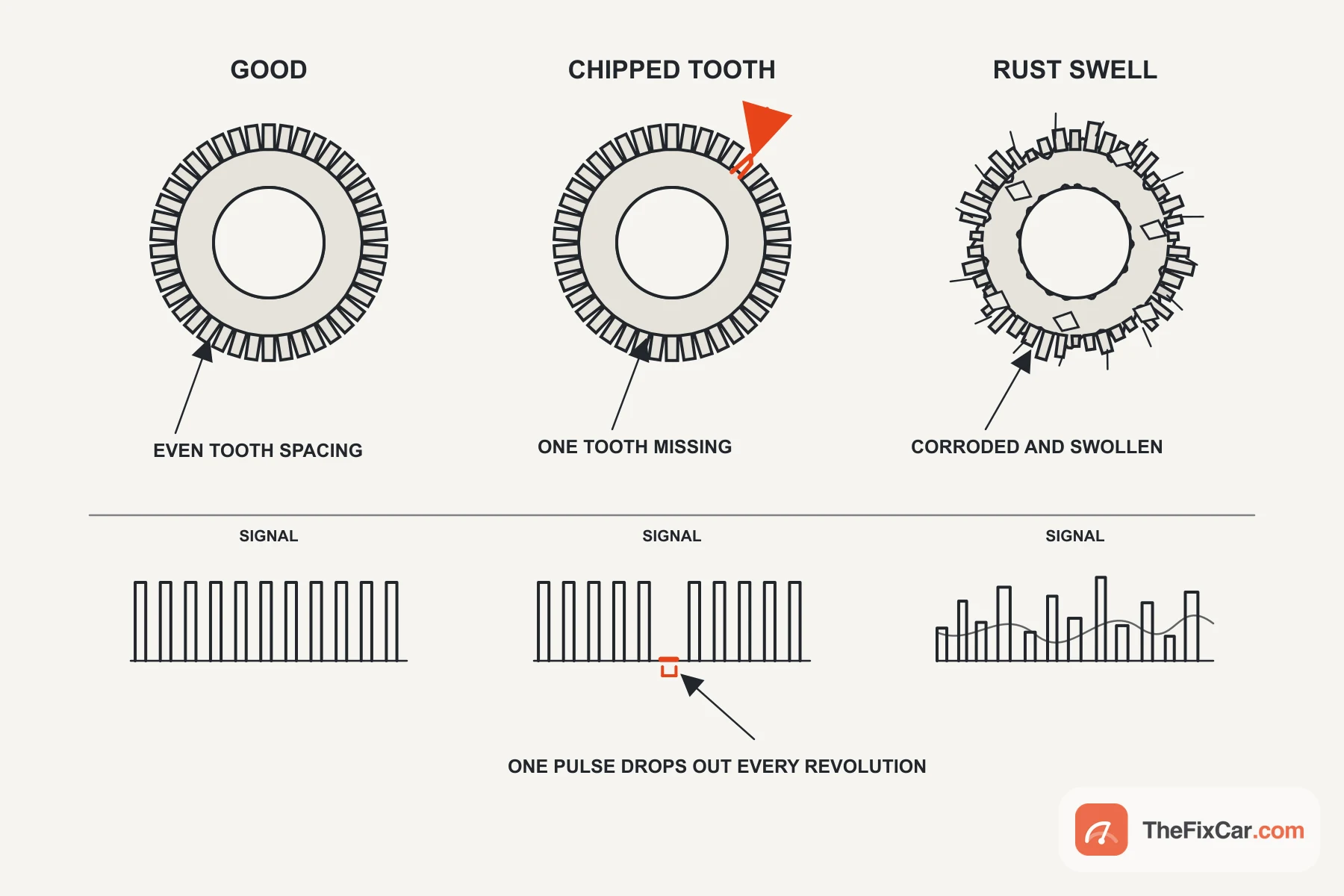
A sensor can be perfect and still report nonsense, because the signal is made in the gap rather than in the sensor. Common ways that gap goes wrong include metal debris collecting on a magnetic tip, a sensor that never seated fully in its bore, and a tone ring that has lost teeth or swollen with rust. Bearing play and a distorted hub belong on the same list.
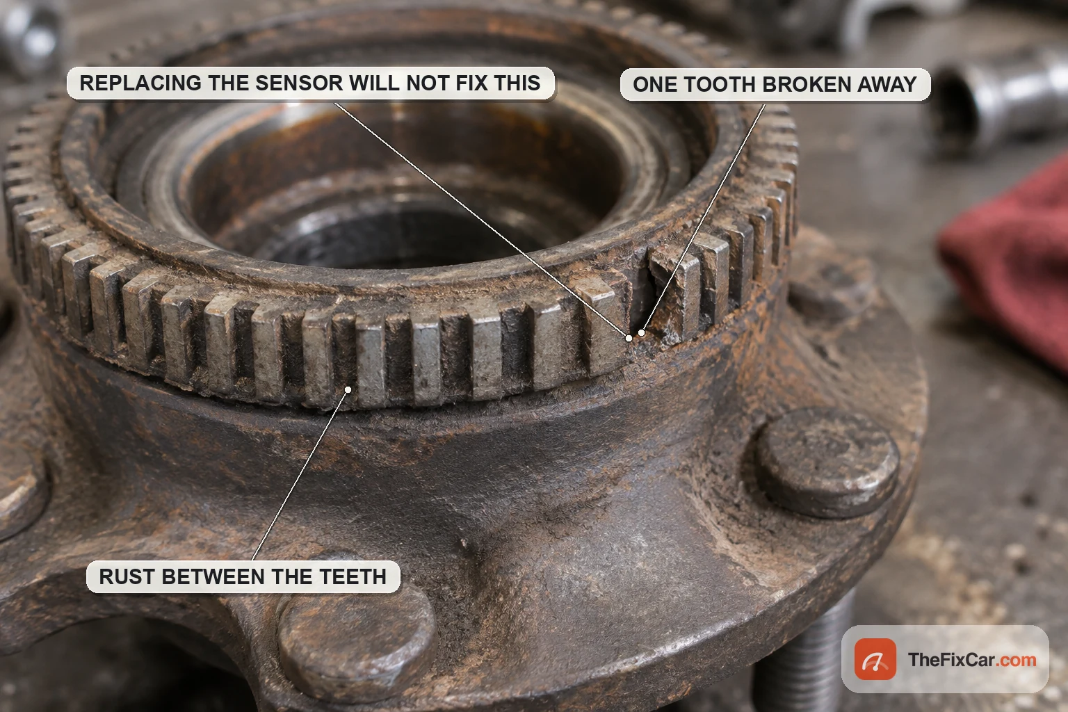
A single chipped tooth on a toothed ring is worth recognising because of the shape of the fault it produces. A damaged tooth usually creates a repeatable dropout or distorted pulse at the same point in each wheel revolution. The exact waveform depends on the sensor and tone ring design, and whether the module flags it depends on its own thresholds. That is a very different pattern from a dead sensor and it often sets a code only above a threshold speed.
Wiring, connectors and grounds
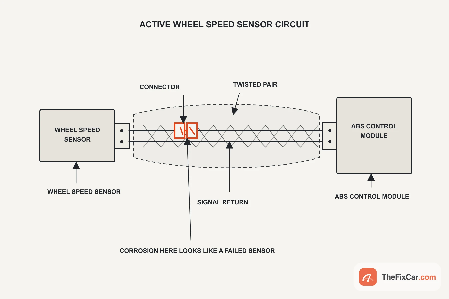
Before condemning a sensor, prove the path to it. Two bulletins give figures for the vehicles they cover, and they show the shape of the test rather than a value to reuse elsewhere. On the chassis harness, each sensor wire should read less than 5 ohms end to end and more than 100 kilohms to chassis ground.[2] On the MV-1, the resistance from the sensor connector to the module connector should be under 2 ohms, and the reference voltage at the sensor connector should sit within 2 volts of specification.[3]
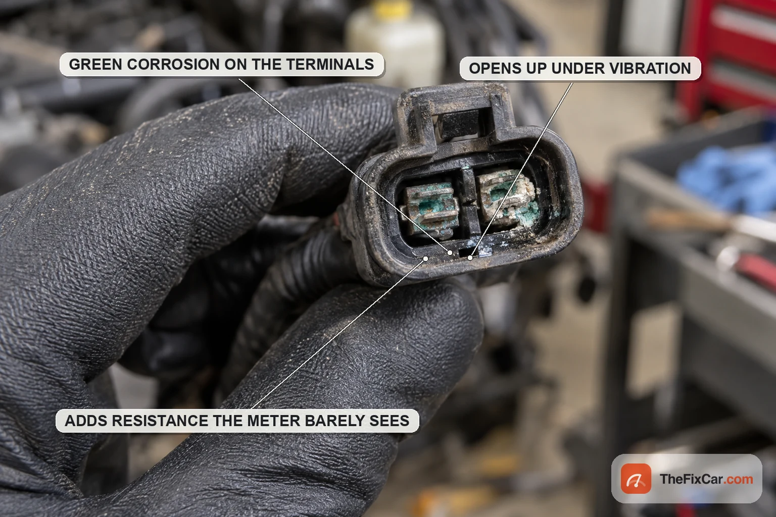
Those two tests catch a failure that readily passes for a bad sensor, though neither will find a joint that only opens under load. A connector can pass a static continuity check and still open when the harness moves. If the dropout follows bumps more closely than wheel speed, flex the harness while watching live data or the waveform.
Conditions the numbers depend on
A specification is only worth as much as the conditions attached to it. Three carry across everything above.
Disconnect a passive sensor before reading resistance. Left plugged in, the meter reads the sensor in parallel with whatever the module presents.[1]
Temperature is part of the passive figure. The Bendix window is quoted for a vehicle at 0 to 100 °F, which is -18 to 38 °C, with the wheel end not hot.[1] Copper climbs with heat, so a reading taken after a drive can put a healthy sensor out of range.
An active sensor is tested with the circuit powered. The MV-1 procedure feeds the sensor from the battery through a fused jumper and reads current while the wheel turns slowly.[3] Connection points and rotation speed differ between documents, so use the procedure written for the application rather than a generic one.
What goes wrong
Reading a passive spec on an active sensor. A wasted afternoon that is easy to walk into. The number looks wrong because the test was wrong, and a good sensor gets replaced.
Measuring resistance through the module. Leave the sensor plugged in and you are reading the sensor in parallel with whatever the module presents. Disconnect it first.[1]
Testing a hot wheel end. A drive raises winding temperature and with it resistance. The Bendix checklist puts a temperature window on the test for exactly this reason.[1]
Blaming the sensor for the ring. A ring pressed onto a hub or moulded into a bearing seal can fail without any noise or play to warn you, and the replacement sensor then reads the same damaged ring.
FAQ
How many ohms should an ABS wheel speed sensor have? Only a passive one has a meaningful answer. Bendix publishes 1200 to 2700 ohms for the WS-24 on commercial vehicles.[1] Passenger car figures differ and belong to your service information.
Can I test an ABS sensor with a multimeter? A passive one, yes: resistance and AC output. An active one needs the circuit powered, and an ohm reading from it is not a test of the sensor unless your service information says otherwise.
How many volts should an ABS sensor produce? For the passive Bendix test, 0.25 volts AC minimum at half a revolution per second by hand.[1] Faster rotation gives more, which is the defining behaviour of a passive sensor.
Why does my ABS light come on only above a certain speed? Speed-dependent faults include a tone ring defect, an intermittent connection, an air gap that is too wide, and bearing play that lets the gap change as the wheel turns. The ring and the air gap need speed before the module can see the error. Wiring is different: it may answer to vibration, load or temperature, and speed is only how you happen to reach those. A sensor that has failed outright is still worth testing for.
Is a two-wire sensor always passive? No. Many active sensors use two wires, drawing supply and signalling on the same pair.[4]
Related brake and ABS guides
Sources & verification
Last technically reviewed: Sep 2026
Reviewed by: Tyler Brandt
Primary references: manufacturer service documents filed with NHTSA, and a sensor manufacturer application note with published electrical characteristics
Image credit: Diagrams drawn for TheFixCar. They illustrate the operating principle and are not to scale.
Suggested citation: TheFixCar, “ABS Wheel Speed Sensor Specs: Resistance, Voltage and Signal,” updated Sep 2026. https://thefixcar.com/specs/abs-wheel-speed-sensor-resistance-voltage-signal-specs/