Search for a VVT solenoid resistance value and you will find confident numbers with nothing behind them. A variable valve timing solenoid, or oil control valve, is not a standardised part: coil resistance, terminal layout, control strategy, and even the physical form of the valve change between manufacturers, between engine families, and sometimes between model years of the same engine.
Every value below is tied to a named source and a named application, with manufacturer documents used wherever they are available. Every vehicle-specific value below comes from a named document you can open yourself, and each application-specific number is labelled with the engine it applies to. Where a value is not published in the documents cited here, that is stated instead of filled in.
Quick answer
There is no universal VVT solenoid resistance specification. Published values differ by application and by the supplier that built the valve: Toyota’s repair manual specifies 6.9 to 7.9 ohms at 20°C (68°F) for the camshaft timing oil control valve on the 2AZ-FE engine[1], while a published reproduction of Kia’s OCV inspection information gives three different ranges depending on which supplier built the valve, and its later service manuals specify 9.4 to 10.4 ohms for other models[2][3]. Use each figure only for the engine and valve it belongs to.
Supply voltage, pin assignment and control strategy are application-specific in the same way. A two-wire valve commonly has one fed circuit and one module-controlled circuit, but the wiring diagram decides which terminal should carry voltage and under what conditions.
Published resistance values by application
| Application example | Valve supplier | Coil resistance | Temperature |
|---|---|---|---|
| Toyota 2AZ-FE camshaft timing oil control valve | Per Toyota repair manual | 6.9 to 7.9 Ω | 20°C (68°F) |
| Kia Alpha 1.6, Gamma 1.6, Theta 2.0 and 2.4 | Denso | 6.9 to 7.9 Ω | 68°F |
| Kia Beta 2.0 | Siemens | 6.8 to 8.0 Ω | 68°F |
| Kia Mu 2.7, Lambda 3.3 and 3.8, Tau 4.6 | Delphi | 6.7 to 7.7 Ω | 68°F |
| Kia Sedona YP and Forte TD, per service manual | Not stated | 9.4 to 10.4 Ω | 20°C (68°F) |
Coverage: the Toyota figure is the 2AZ-FE repair manual page; the three supplier ranges come from Kia’s OCV inspection information for the CVVT-equipped models it lists; the 9.4 to 10.4 ohm figure is from the Sedona YP and Forte TD 2014 to 2018 service manuals. These are examples, not a universal VVT solenoid resistance range. Match the engine, the model year and the valve before using any value. The reproduced Kia figures move with the supplier that built the valve[2], which is why a figure from another vehicle cannot be assumed to apply.
What is published and what is not
| Value you want | Publicly published? | Where it actually lives |
|---|---|---|
| Coil resistance | Yes, on some applications | The engine-specific OEM service specification, at a stated temperature |
| Supply voltage | Partly | Wiring diagram: which side is fed and under what enable conditions |
| Current draw | Not in the documents cited here | OEM service information or a supplier data sheet for that exact part |
| Duty cycle | As live data | Scan tool parameter, commanded by the module, not a target you set |
| Test values | Sometimes | OEM bulletins and pinpoint tests, where one is published for a named application |
| Pinout | Yes | Connector charts in service bulletins and wiring diagrams |
| Torque | Yes, in the procedures cited here | OEM repair procedures for the applications they cover |
| O-ring dimensions | Not in the examples cited here | Handled by part number and by handling instructions in those documents |
Disclaimer: every figure in this article is tied to the source listed for the application it covers. Some are manufacturer documents and some are published reproductions of manufacturer service information. None of it transfers to another engine, and none of it replaces the service information for the vehicle in front of you.
Coil resistance
What the measurement covers. On a two-terminal valve, an ohmmeter across the solenoid terminals reads the winding and the terminal path, nothing else. ASE’s certification material for advanced engine performance separates powertrain mechanical problems from electrical and electronic ones in variable valve timing and variable valve lift systems[5], and that split is the point here: a resistance reading covers the electrical half, so a valve can measure correctly and still have a spool that does not move freely.
What a real OEM spec looks like. Toyota’s inspection step for the 2AZ-FE camshaft timing oil control valve is short: measure between terminal 1 (+B) and terminal 2 (GND), expect 6.9 to 7.9 ohms at 20°C (68°F), and, as the next step of Toyota’s own procedure for that engine, replace the valve assembly if the result falls outside the range[1]. Named terminals, a named engine, a stated temperature. A figure quoted without those three things is hard to use as one.
Why the valve supplier changes the number. A published reproduction of Kia’s OCV inspection information covers models fitted with valves from three different suppliers and gives a different range for each at 68°F: 6.9 to 7.9 ohms for Denso valves on Alpha 1.6, Gamma 1.6 and Theta 2.0 and 2.4 engines, 6.8 to 8.0 ohms for Siemens valves on the Beta 2.0, and 6.7 to 7.7 ohms for Delphi valves on Mu 2.7, Lambda 3.3 and 3.8 and Tau 4.6 engines[2]. Later Kia service manuals list a different range, specifying 9.4 to 10.4 ohms at 20°C for the Sedona YP and Forte TD[3]. The published range differs within a single manufacturer’s own service information.
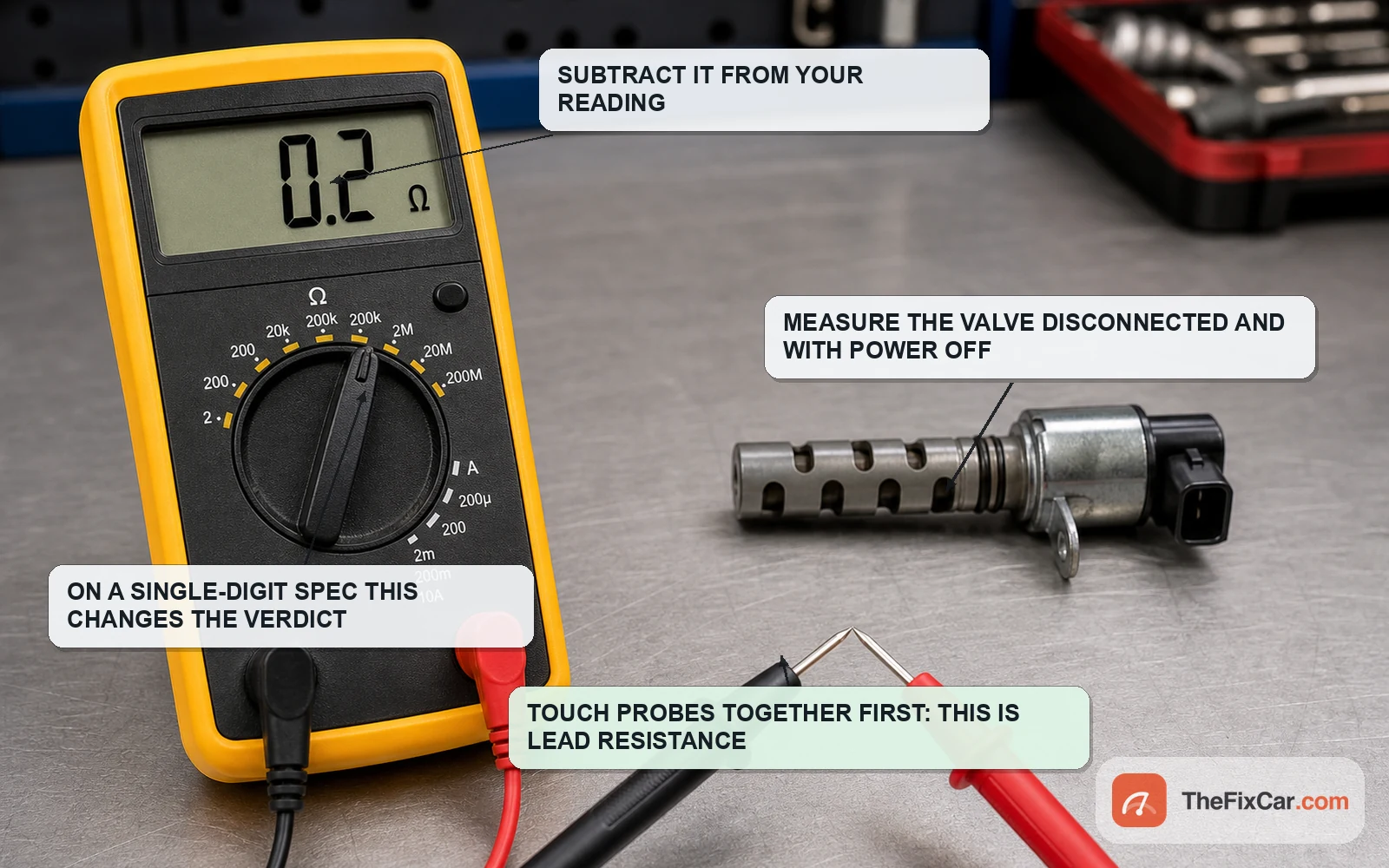
Why a borrowed number can mislead. Copper winding resistance rises with temperature, so a usable resistance specification should state or assume a reference temperature. A figure copied from another engine can put a healthy valve outside a range that does not apply to it, or a failing one inside it. On low-resistance specifications, test lead resistance can be large enough to change the verdict, so zero the meter or subtract the measured lead resistance[13].
A related example from a different solenoid. General Motors specifies 10 to 30 ohms between control terminal 2/B and ignition terminal 1/A of the engine oil pressure control solenoid valve on the 1.2L turbo engine[8]. That is an oil pressure control solenoid rather than a cam phasing valve, and it appears here only to show how far a published range can sit from the VVT figures above.
Supply voltage and control signal
The common two-wire layout. Many two-wire hydraulic valves use one fed side and one module-controlled side, with the module varying on-time to influence spool position. Both supply-side and ground-side switching are used, so the wiring diagram for your engine decides where you put the probe.
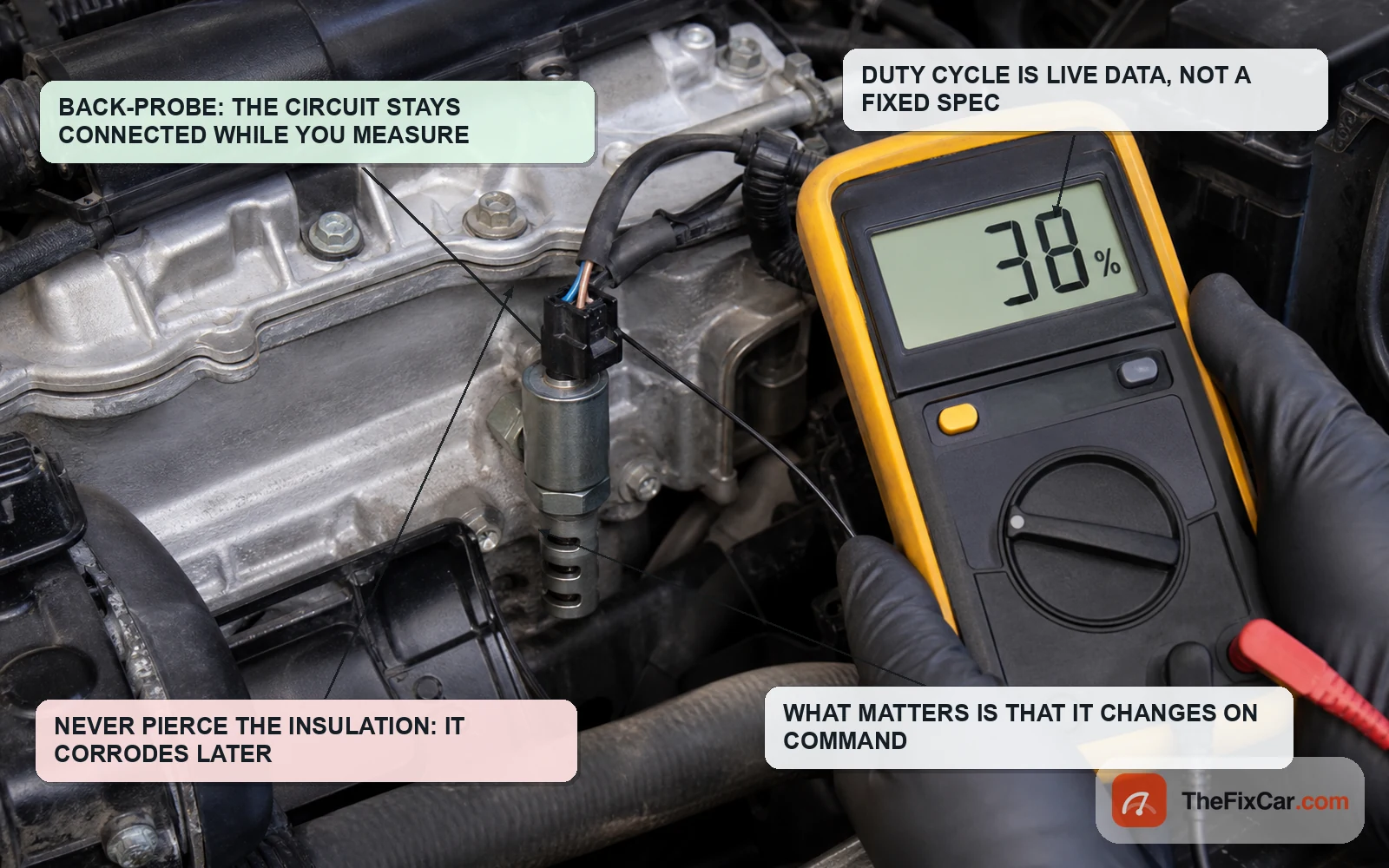
Check for system voltage only where the wiring diagram says it should be present. The feed on a typical hydraulic oil control valve sits at system voltage when it is fed. Whether it is fed with the key on and the engine off is a property of the circuit design, and some systems only power it once enable conditions are satisfied, so a missing reading at key-on is not automatically a fault.
A bench voltage test is not an operating voltage reading. Toyota’s inspection procedure for the 2AZ-FE oil control valve has the technician apply battery voltage across the terminals and watch that the spool valve operates[1]. That is a movement check on a removed valve, not a statement about what a meter should read across the valve on a running engine. Kia’s technician publication describes the other side of it: the PCM grounds the OCV with pulse width modulation[4]. Expecting a steady 12 volts across a PWM-controlled valve while the engine runs confuses the two tests.
Duty cycle is data, not a specification. The module commands a percentage, and the valve and cam system respond only when the electrical, hydraulic and mechanical sides are all working. There is no universal percentage to look up. Where an OEM procedure publishes a commanded range or an active-test value, use it for that application only. Otherwise, and only under the enable conditions the OEM procedure gives, what you check is that the commanded value changes when the module asks for a different cam angle, and that actual cam position follows it. Many systems require specific oil temperature, engine speed and load conditions before meaningful phasing is commanded at all, which is why a warm engine at idle can show a flat command and still be healthy.
Variable force versus on and off. ASE defines a variable force solenoid as an electro-hydraulic device that controls fluid pressure proportionally or inversely proportionally to a signal from a control module[5]. That definition explains why a proportional solenoid reading cannot be read as a simple on or off command. For any specific VVT circuit, take the OEM description for that engine before interpreting a duty cycle figure.
Current draw
The documents cited here do not publish one. The manufacturer bulletins used throughout this article give resistance limits, torque figures and test procedures, but no VVT solenoid current-draw specification. If you plan to diagnose on current, take the figure from OEM service information or a supplier data sheet for that exact part, and treat an online amperage number with neither behind it as unverified.
What you can do instead. A low-amperage current clamp on the control wire shows the current actually flowing in that circuit, and comparing confirmed matching circuits bank to bank on the same engine can be useful as a clue, though it is not proof by itself, and only where the service information confirms the two are the same part. Only bench-power a valve where the service information for that exact part allows it and gives the voltage, the polarity, a current limit or duty cycle, and a maximum on-time.
OEM VVT diagnostic values and test procedures
Ford: cycle the solenoid ten times before condemning it. For 2015 to 2021 Ford and Lincoln vehicles showing VCT codes across the P0011 to P0025 range, Ford’s SSM 50067 describes a listed condition in which small debris can cause the VCT solenoid to stick, and directs the technician to pinpoint test HK12 to cycle the affected solenoid ten times to attempt to clear it before any component diagnosis or replacement[10]. Ten cycles is a real, quotable test value, and it belongs to those models.
Subaru: camshaft position learning values. Subaru’s AVCS bulletin publishes a normal range for what it calls the VVT initial position learning value, stated as plus and minus 10 degrees from the standard angle, which is the 20 degree window shown for each model below. The bulletin uses it as a chain timing check, one step ahead of suspecting the valve[6].
| Subaru AVCS camshaft learning values: a mechanical timing check, NOT solenoid resistance | ||||
|---|---|---|---|---|
| Subaru model (per bulletin 02-163-16R) | Intake normal range, degrees | Intake standard, degrees | Exhaust normal range, degrees | Exhaust standard, degrees |
| Legacy / Outback 2.5L NA | 21.5 to 41.5 | 31.5 | Not listed | Not listed |
| Forester 2.5L NA | 21.5 to 41.5 | 31.5 | Not listed | Not listed |
| Forester 2.0L DIT | 68.0 to 88.0 | 78.0 | 97.0 to 117.0 | 107.0 |
| WRX 2.0L DIT | 68.5 to 88.5 | 78.5 | 98.5 to 118.5 | 108.5 |
| Impreza / XV 2.0L NA | 50.5 to 70.5 | 60.5 | 79.5 to 99.5 | 89.5 |
| BRZ 2.0L NA | 52.0 to 72.0 | 62.0 | 78.0 to 98.0 | 88.0 |
Values in degrees, read with Subaru Select Monitor. The bulletin covers FA and FB engine models: Forester 2.5L from 2011MY, Impreza 2.0L from 2012MY, Legacy, Outback, XV Crosstrek and BRZ from 2013MY, Forester 2.0L DIT from 2014MY, WRX from 2015MY and the 2019MY Ascent. They describe chain timing, not solenoid condition.
Ford: which solenoid the code pair points at. On 2016 F-150, Expedition, Navigator and Transit with the 3.5L GTDI engine under 3,200 km, Ford pairs these code combinations to a specific diagnostic path: P0011 with P0016 directs the technician into the bank 1 intake VCT solenoid circuit and mechanism diagnostic path, and P0015 with P0017 into the bank 1 exhaust equivalent[12]. That direction does not by itself prove the solenoid is bad: wiring, connector condition, oil control, mechanical timing and actuator faults still have to be separated by the Ford pinpoint test. Useful as an illustration of how banks and camshafts map to codes, and application-specific like everything else here.
General Motors: a mechanical check with no meter involved. On some GM engines the valve is built into the mounting bolt. Bulletin 21-NA-146 traces P0011 and P0014 to a broken spring in a camshaft position actuator valve solenoid bolt, and has the technician remove the actuator magnets and compare the travel and feel of the two bolt plungers against each other by finger[9]. No resistance value exists for a fault like that.
Pinout and connector values
Two pins is common on hydraulic oil control valves, and the numbering is not universal. Toyota identifies the 2AZ-FE oil control valve terminals as 1 (+B) and 2 (GND), and the resistance specification is written against that pair[1]. Elsewhere the terminal identification comes from the connector chart for your vehicle. Subaru’s bulletin prints a full chart mapping each oil control solenoid through the harness[6].
| Circuit (Impreza / XV excluding hybrid, 12MY to 14MY) | ECU connector / pin | Bulkhead connector / pin | Actuator connector / pin |
|---|---|---|---|
| Intake oil control solenoid, left bank | B134 / 17 | B21 to E2 / 32 | E37 / 1 |
| Intake oil control solenoid, right bank | B134 / 34 | B21 to E2 / 21 | E38 / 1 |
| Exhaust oil control solenoid, left bank | B134 / 5 | B21 to E2 / 42 | E66 / 1 |
| Exhaust oil control solenoid, right bank | B134 / 7 | B21 to E2 / 7 | E63 / 1 |
The same bulletin lists different pin assignments for 15MY and hybrid variants of the same models, which is the clearest possible warning against reusing a pinout across model years.
Harness limits get published even where a coil resistance figure does not. For the AVCS oil control solenoid circuit checks in Subaru’s bulletin, along the connector path its own chart defines, more than 1 ohm between the oil control valve and the ECU is treated as a fault to repair[6]. General Motors uses a similar style of limit on a related circuit, calling for less than 10 ohms between the low reference circuit terminal and the ECM connector terminal on the 1.2L turbo engine[8].
Connector condition has its own checklist. GM’s procedure for the related oil pressure control solenoid opens by removing the solenoid connector and inspecting for proper terminal tensions, crimps and locks, then manipulating the harness while watching the resistance reading to catch an intermittent[8]. Terminal tension is on that inspection list for a reason: a static reading taken through a loose terminal can look correct at rest.
Torque specifications
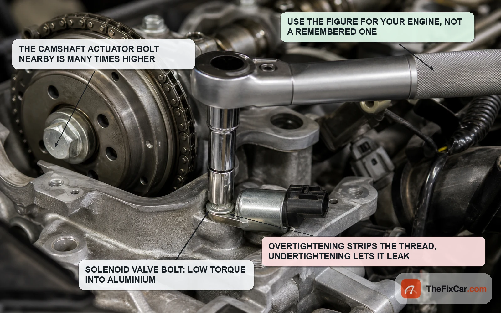
Manufacturer procedures publish these values by application. General Motors’ engine bulletin 08-06-01-011K gives the figures below for the engines it covers. In these examples the solenoid valve bolt is a small fastener, and the gap between it and the camshaft actuator bolt is a good illustration of why the service procedure matters.
| Fastener | Torque |
|---|---|
| Toyota 2AZ-FE camshaft timing oil control valve bolt | 9.0 N·m (92 kgf·cm, 80 in·lbf) |
| GM intake and exhaust camshaft position actuator solenoid valve bolts | 10 N·m (89 lb in) |
| GM intake and exhaust camshaft position sensor bolts | 10 N·m (89 lb in) |
| GM intake and exhaust camshaft position actuator bolts | 58 N·m (43 lb ft) |
Toyota figure from the 2AZ-FE repair manual page[1], GM figures from bulletin 08-06-01-011K, which covers 2007 to 2010 GM models built with the 2.8L or 3.6L High Feature V6 (RPOs LP1, LLT, LY7)[7]. The Toyota and GM solenoid bolt figures sit close to each other, and both are far below the GM camshaft actuator bolt on the same engine. Torque for your engine still comes from your service information.
Related mechanical limits from the same document. That bulletin also gives a camshaft end play threshold of 0.40 mm (0.016 in) as a decision point during diagnosis, and a clearance check where a 2.0 mm hex wrench for the Delphi four-screw actuator, or 2.5 mm for the Aisin five-screw actuator, should not fit between the camshaft position actuator and the front camshaft cap[7]. The bulletin gives a different clearance figure for each of the two actuator designs it names.
O-ring and seal data
Handling instructions exist, dimensions generally do not. Toyota’s installation step for the 2AZ-FE oil control valve is to apply a light coat of engine oil to the O-ring, and to make sure the O-ring is not cracked or jammed as the valve goes in[1]. No size is given, because the seal is a service part rather than a measurement.
Ford lists the seal separately from the valve. The bulletin for DTCs P0390 and P0394 on the 2018 F-150 and 2018 to 2019 Mustang 5.0L gives the exhaust VCT oil control solenoid as HL3Z-6M280-A and the VCT solenoid valve cover seal as BR3Z-6C535-A[11], so the seal can be ordered on its own.
Sometimes the valve is the replacement item. Honda’s bulletin for leaking front rocker arm oil control valves on 2008 to 2012 Accord V6 and related models attributes the leak to a deteriorated gasket or a gasket groove out of specification, and replaces the valve rather than the seal alone[14]. A generic O-ring does not address a groove that is out of tolerance.
How to check
- Get the real specification first. Look up your exact year, engine and market in the service information before touching a meter. Without a target value a resistance reading tells you almost nothing.
- Inspect the connector before measuring. Terminal tension, crimps, locks, and any oil inside the housing. Fix what you find before you trust a reading through it[8].
- Null your leads, then measure the coil. Key off, solenoid disconnected, probes across the coil terminals identified for your valve, lead resistance subtracted[13]. Compare to the specification at its stated temperature.
- Check the circuit, not just the component. With the circuit de-energized and both connectors unplugged, measure resistance from the solenoid connector to the module against the published limit, then wiggle the harness while watching for the reading to jump[8].
- Watch commanded against actual. Under the enable conditions the OEM procedure specifies, log desired and actual cam angle. A command that moves while actual position does not follow means coil resistance alone has not found the fault: keep separating circuit, oil control, actuator and mechanical timing causes.
- Use the OEM test before condemning the part. Where the manufacturer publishes one, run it: cycling a sticking Ford VCT solenoid ten times is a documented step, not a workaround[10].
What goes wrong
A borrowed resistance value condemns a good valve. Borrowed specifications lead to unnecessary replacement. A figure from a different engine, quoted with no temperature and no source, can lead to a healthy solenoid being replaced and the real fault stays in the car.
The valve is not the shape you expect. On the GM design covered by bulletin 21-NA-146 the working parts sit in the mounting bolt, with a spring-loaded plunger you compare by feel[9]. On those applications, assuming a removable two-wire spool valve sends the diagnosis down the wrong path.
Pinouts change inside one model line. Subaru lists different pin assignments for the same circuits between 12MY to 14MY and 15MY on the same models[6]. Back-probing the pin a forum post named is how a good circuit gets recorded as an open.
Debris, not failure. For the vehicles and symptoms covered by SSM 50067, Ford describes small debris sticking the solenoid as a possible cause behind the listed P0011 to P0025 VCT code condition, which is why cycling it is the documented first move[10]. Replacing the valve before running that documented cycling step skips the bulletin’s own first move.
Over-torquing a 10 N·m fastener. Small fasteners into a soft casting strip easily, and on that GM engine there is a factor of nearly six between the solenoid valve bolt and the camshaft actuator bolt[7]. Reaching for the same setting on both is an expensive mistake.
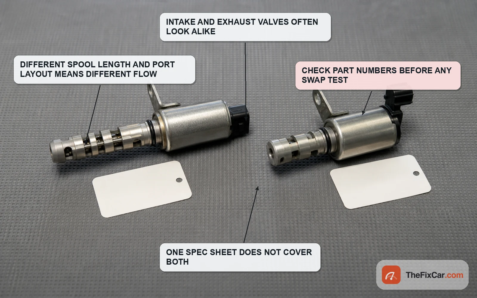
Assuming intake and exhaust valves interchange. They can carry different part numbers, flow characteristics and default positions. A swap test is only valid where the parts catalog or service information confirms interchangeability.
FAQ
What should a VVT solenoid read in ohms? Whatever your engine’s service information specifies at the stated temperature. Published examples can overlap and still carry different pass and fail limits: 6.9 to 7.9 ohms at 20°C for the Toyota 2AZ-FE valve[1], 6.7 to 7.7 ohms for Delphi valves and 6.8 to 8.0 ohms for Siemens valves on the Kia applications listed in the reproduced Kia OCV inspection information[2], and 9.4 to 10.4 ohms on the Sedona YP and Forte TD[3]. A valve reading 7.2 ohms passes on one of those engines and fails on another.
How many volts should a VVT solenoid get? On a typical two-wire hydraulic valve the fed side sits at system voltage while the module switches the other side. Whether that supply is present with the key on and the engine off depends on the circuit design, so check the wiring diagram rather than assuming a missing reading is a fault.
What duty cycle is normal for a VVT solenoid? There is no normal figure to target. Duty cycle is what the module commands under the conditions of the moment, and many systems command little phasing until oil temperature, engine speed and load conditions are met. Judge whether the command changes and whether actual cam angle follows it.
How much current does a VVT solenoid draw? None of the manufacturer documents cited here publish a figure. Treat online amperage figures without a supplier data sheet behind them as unverified, and compare confirmed matching circuits bank to bank on the same engine instead, and only where service information confirms the parts and circuits are equivalent.
What is the torque for a VVT solenoid bolt? Low, and engine-specific. GM specifies 10 N·m (89 lb in) for the camshaft position actuator solenoid valve bolts on the engines its bulletin 08-06-01-011K covers[7]. Use the figure for your engine, not that one.
What size O-ring does a VVT solenoid use? The manufacturer examples cited here give handling instructions and part numbers rather than a dimension. Toyota calls for a light coat of engine oil on the O-ring and a check that it is not cracked or jammed[1], and Ford lists the VCT solenoid seal separately from the solenoid[11]. Where the groove itself is out of specification, the valve is the replacement item[14].
Are intake and exhaust VVT solenoids the same part? Not necessarily. Verify part numbers before swapping them, because part number, connector, installation position and service information can distinguish intake from exhaust valves even where the bodies look similar.