This guide covers two-wire NTC ambient air temperature sensors: thermistors that measure outside temperature for the dashboard display and, depending on the vehicle, for the climate control and other systems. Where the sensor sits, which module reads it and what uses the reading vary by vehicle; the examples below come from BMW, GM, Audi, Tesla, Mitsubishi and the sensor maker Hella.
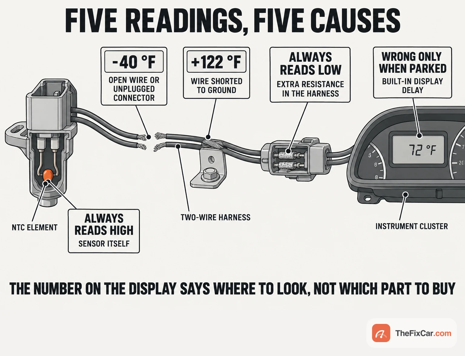
An implausible reading can come from the sensor, the wiring, the mounting conditions or the display processing, and BMW’s bulletin on implausible outside temperature readings shows how the displayed value helps direct the checks: it lists −40 °F, +122 °F, a display stuck low, a display stuck high and a reading that is wrong only while the car is parked, each paired with a different place to look.[1] The required test order and test points are the vehicle’s own, and the examples here show how two carmakers apply them.
Quick answer
First decide whether the reading is wrong or merely slow. Carmakers deliberately hold and smooth the outside temperature after a start, so judge the display only after the car has met its own update conditions. If the discrepancy remains, read the number: on the BMW applications cited, an extreme value such as −40 °F or +122 °F directs the technician to the circuit, while a small, steady offset can be heat exposure, display filtering, sensor mounting, sensor drift or harness resistance. Where the carmaker specifies it, one resistance measurement at the module connector checks the sensor and harness together against the vehicle’s temperature chart: BMW’s chart gives 6,166 to 6,322 Ω at 68 °F for its listed models, measured at the cluster connector with the sensor connected, and the chart is BMW’s own, not a value for other cars.[1] A display value or a trouble code alone does not identify a failed sensor; access and replacement steps are the vehicle’s own, with the Tesla procedures below as the documented example.
What each test can and cannot tell you
| Test | What it tells you | What it does NOT prove |
|---|---|---|
| Display and sensor data after the vehicle’s update conditions are met, against an independent thermometer away from the car’s heat and direct sun | Whether the reading stays inconsistent with the reference under the carmaker’s specified conditions; sensor data and the filtered display are compared separately where both are available | Where in the circuit the fault is, or whether a few degrees of error is sensor drift, mounting, or harness resistance |
| Combined resistance at the cluster or module connector, sensor still connected, circuit de-energised | Whether sensor plus harness together are plausible against the chart at the sensor’s stabilised temperature, at that moment | Which of the two is wrong when the number is off; intermittent faults; sensor response; anything in the module or display processing |
| The wiring checks in the vehicle’s procedure: continuity end to end, then separate checks for shorts to ground, to voltage and between the wires | Whether each wire is continuous and isolated under the conditions tested | Terminal contact quality under vibration and road spray, or a fault that only appears with the harness flexed |
| Sensor alone at two known temperatures | Whether the thermistor follows its chart at the points tested | Response time, behaviour between those points, and the harness it came out of |
What the display reading can suggest
For the Hella sensor described here, the receiving circuit is a voltage divider: Hella’s data sheet describes an NTC element in series with a constant resistor, with the voltage divider law turning the measured voltage into a resistance and the resistance curve turning that into a temperature.[5] A cold thermistor has high resistance, so an open wire or an unplugged connector looks like a very high resistance to such a circuit. For its covered models, BMW lists an open harness or a disconnected connector when the display reads −40 °F, a harness short to ground at +122 °F, excessive harness resistance when the display is constantly too low, and the sensor itself when it is constantly too high; these are directions for further testing, not proof of a failed part, and the value another module shows for an open circuit depends on its own fault handling.[1] The divider arithmetic is worked through on the engine coolant temperature sensor specs page; the NTC principle applies here too, but the circuit details and the resistance chart must match the vehicle.
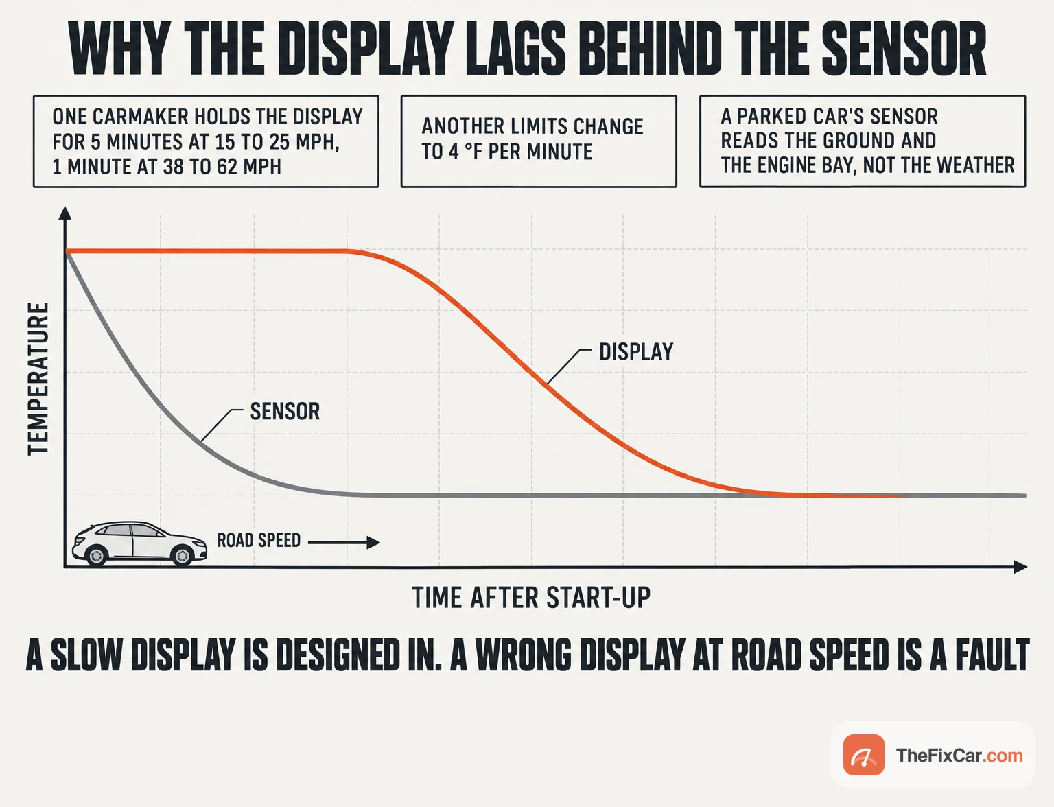
Readings that are inaccurate while parked or slow to change after a start can be normal heat exposure and display filtering rather than a fault. GM’s PI0233E, for the listed 2010 to 2016 Buick, Chevrolet and GMC models, explains why: a parked car’s sensor reads sunlight on the bumper and heat from a warm engine, so the display is held until the car has been moving: for the listed models, 5 minutes at 15 to 25 mph and 1 minute at 38 to 62 mph before the first update, and the bulletin tells technicians not to replace the cluster or the sensor for that complaint.[2] Audi’s bulletin, for 2008 to 2020 models except the e-tron, limits the display to 4 °F per minute and holds it in other ways while the car is slow or warm.[3] The display can be filtered on purpose, so verify the update conditions before condemning the sensor. Software can also produce an incorrect display: a 2014 GM bulletin for 2015 Cadillac CTS, XTS and SRX clusters built before September 8, 2014 describes a display showing 18 °F when the outside temperature was 80 °F and fixes it with a cluster calibration, not a sensor.[4] Confirm that the behaviour matches the applicable service information before ruling a fault out or in.
Where it sits
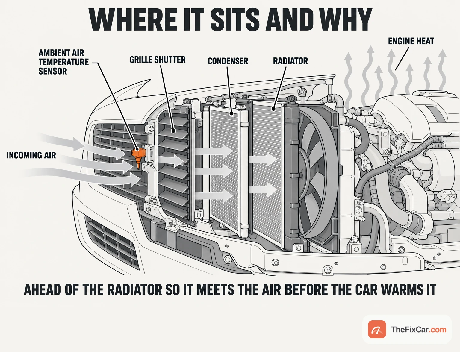
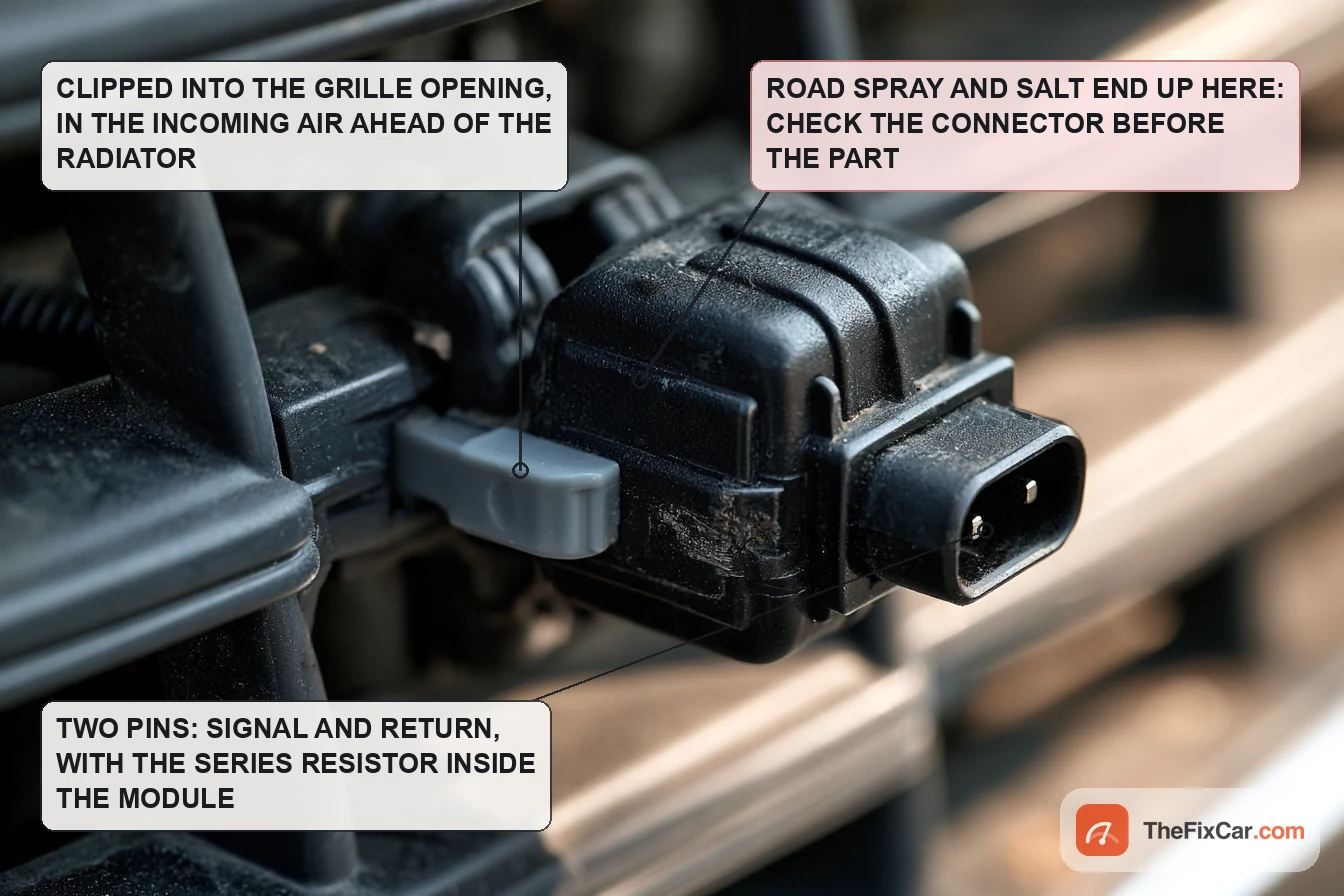
The examples here mount the sensor near the front bumper or grille, where moving outside air reaches it before the car has warmed it; the vehicle’s service information gives the actual location. Hella’s data sheet puts the typical installation space in the front bumper and rates the housing IP67.[5] BMW’s bulletin adds the practical consequence for its models: a stationary car’s sensor is primarily reading the ground temperature, and the sensor is most accurate at road speeds of 50 mph or higher.[1]
Tesla documents the location precisely. On the 2020 to 2024 Model Y the sensor clips to the active grille shutter under a small cover; the procedure removes the underhood storage unit, releases the cover with a small flat-bladed tool, disconnects the connector and releases the clip.[7] On the 2024 and later Model 3 the sensor is also under a cover on the active grille shutter, retained by clips.[8] In Mitsubishi’s 2009 service information (the page names the system, not the model) the sensor is connector A-36, two terminals, wired to terminals 7 and 14 of the ETACS-ECU at connector C-312, and the climate codes B1034 and B1035 cover a short and an open in that circuit.[6] Which module reads the sensor decides which scan tool menu shows it: on that Mitsubishi it is the body and climate side, and the module can share the value with others over the vehicle network.
How to test it
Before testing, confirm the vehicle’s wiring diagram, connector identification, resistance chart and diagnostic procedure, and follow its instructions for power isolation, module sleep, connector handling and any display reset. Resistance mode only on a circuit confirmed de-energised, with probes that do not spread the terminals.
- Rule out the delay. Follow the vehicle’s display-update behaviour, as in the GM and Audi examples above, and compare the result with an independent thermometer away from the car’s heat and direct sunlight. BMW’s cluster test function has a software reset that forces an immediate reading on its covered models.[1] If the reading and the update behaviour match the carmaker’s criteria and nothing else points to a fault, replacement is not indicated.
- Read the codes and the live value. Look in the module that owns the sensor: the instrument cluster on the BMW (fault 931B for an open or a short), the ETACS-ECU on the Mitsubishi (B1034 short, B1035 open or poor connection).[1][6] Mitsubishi’s chart checks the CAN bus and rechecks the code before touching the harness, and treats a code that does not return as intermittent.[6]
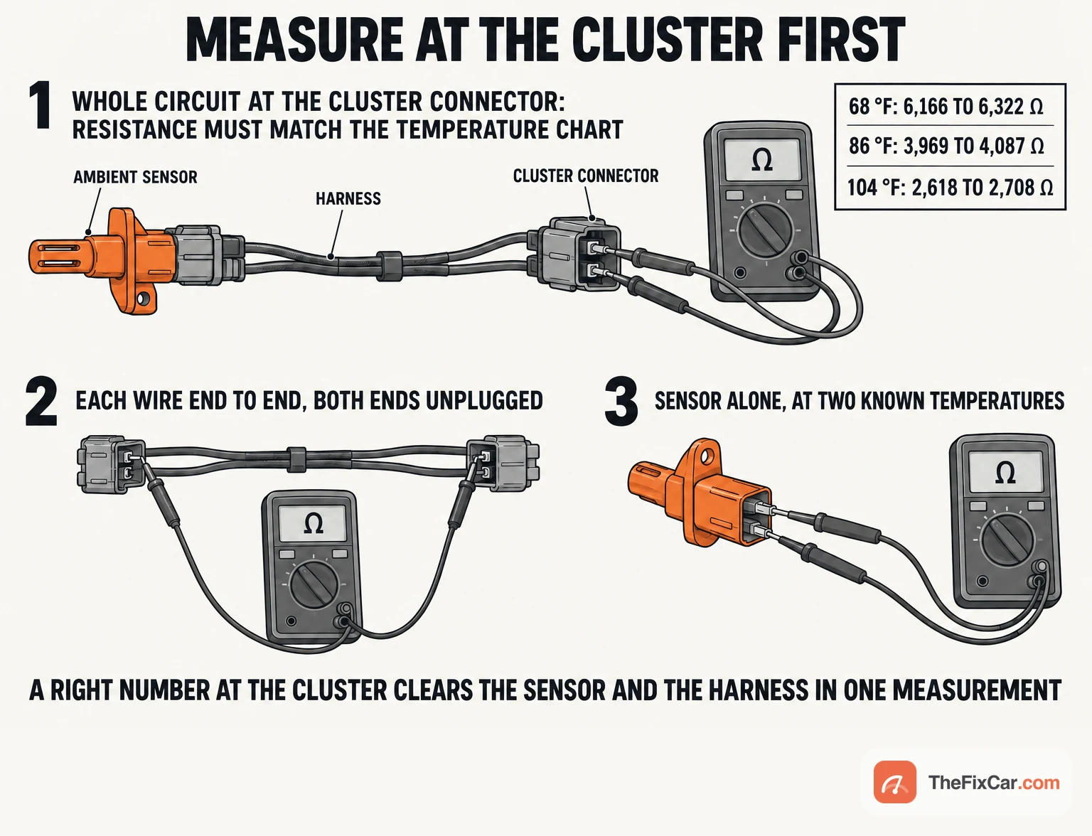
- Measure the combined circuit if the procedure specifies it. With the circuit de-energised and the module connector unplugged, measure resistance across the two sensor pins on the harness side, sensor still connected at the far end. BMW’s bulletin does this first and compares it with its chart: 16,116 to 16,530 Ω at 32 °F, 6,166 to 6,322 Ω at 68 °F, 4,930 to 5,067 Ω at 77 °F, 3,969 to 4,087 Ω at 86 °F, 2,618 to 2,708 Ω at 104 °F, for the sensor at its stabilised temperature.[1] A reading inside the window shows the combined resistance is plausible at that temperature and at that moment; it does not rule out an intermittent fault, slow response or a problem in the module or display. A reading far outside the window directs the next checks; it does not name the failed part.
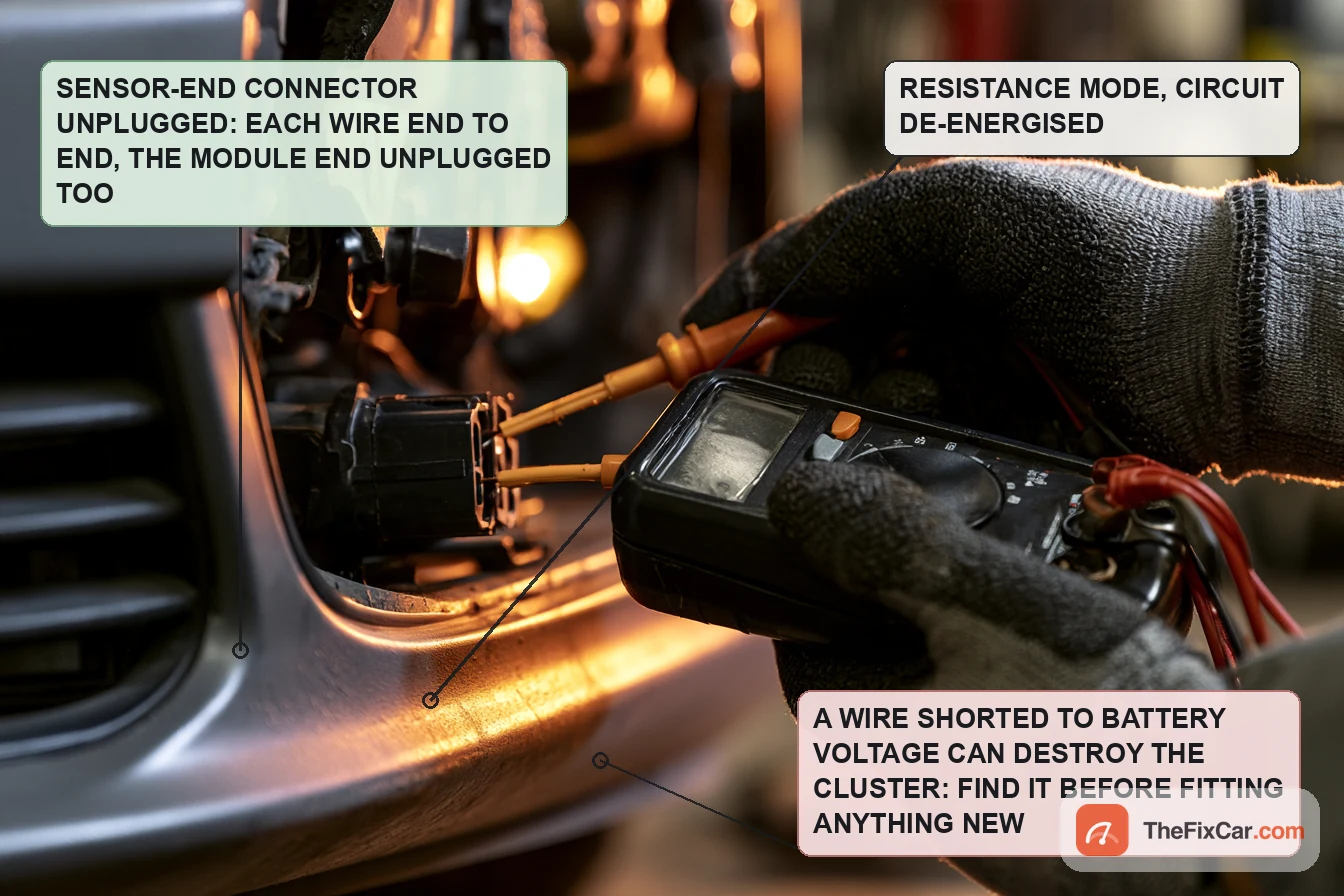
- Check the wiring as the procedure lays it out. With the circuit isolated and confirmed de-energised, unplug at both ends and check each wire for continuity, then separately for isolation from ground, from the other wire and, in voltage mode under the power state the procedure specifies, for unwanted voltage. BMW warns that a harness shorted to battery voltage damages the cluster, which is why its bulletin forbids fitting a new cluster for testing before the harness has been checked.[1] Mitsubishi’s chart checks the same two lines between A-36 and C-312 for opens and shorts.[6] Flex the accessible harness under the bumper while measuring; it lives in the spray.
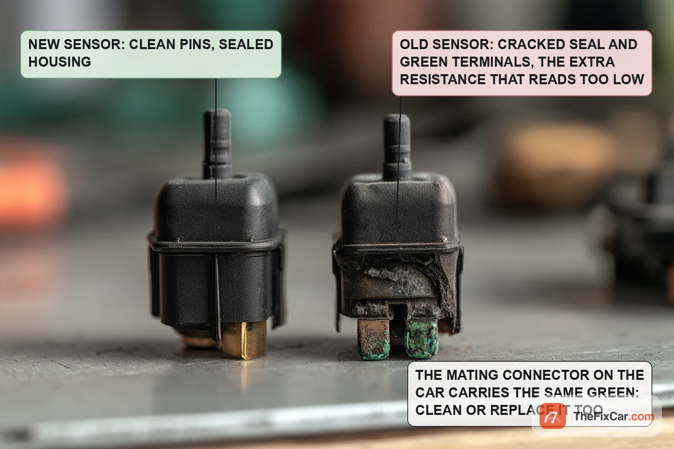
- Inspect the connector. Corrosion, road salt contamination and damaged pins are the BMW bulletin’s named causes at the sensor-side connector. Follow the carmaker’s connector-repair procedure, with an approved cleaner only where it permits one, and repair or replace damaged terminals and seals; substitute a known-good sensor only where the procedure allows it and the part is confirmed interchangeable.[1]
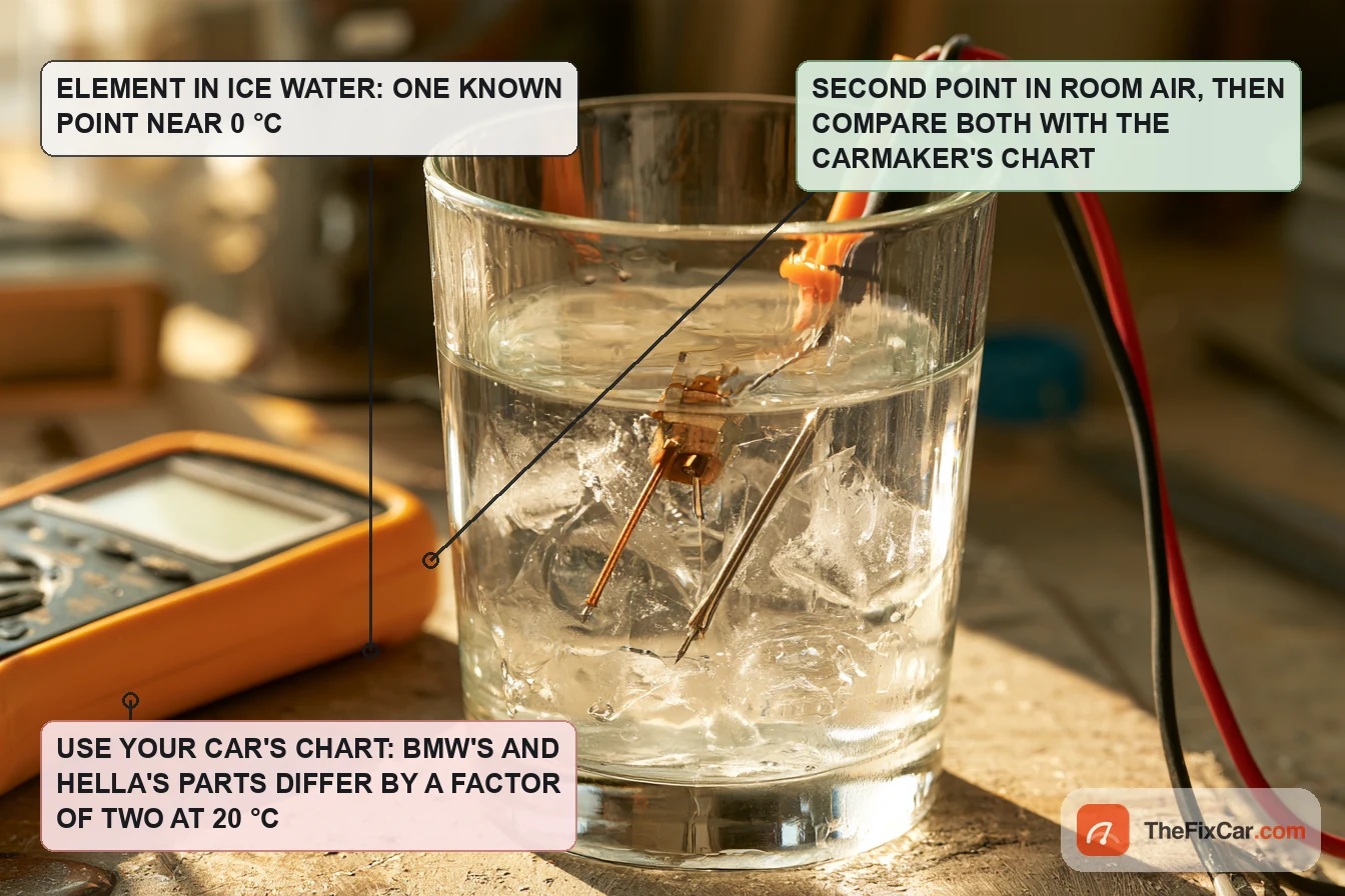
- Test the sensor separately when directed. Mitsubishi measures resistance between the sensor’s two terminals at no fewer than two temperatures and compares with its graph, within the graph’s range.[6] Let the sensor and the thermometer stabilise under the same conditions before comparing. Use the temperature-conditioning method the sensor’s service information specifies, and immerse it only where that information permits; an IP67 rating describes the housing, not the test method. Use your own car’s chart: BMW’s circuit reads 6,166 to 6,322 Ω at 68 °F where Hella’s 6PT 009 522-011, with its built-in linearising resistor, reads 2,792 Ω at the same 20 °C, and both are correct for their own circuit.[1][5]
How to replace it
The steps below summarise the cited Tesla procedures. For another vehicle, its service information gives the access, any power isolation, the sensor attachment and any post-repair setup.
- Get to the grille shutter. On the 2020 to 2024 Model Y and the 2024 and later Model 3, remove the underhood storage unit; the sensor and its cover are then in reach on the active grille shutter.[7][8]
- Release the cover. Tesla’s Model Y step uses a small flat-bladed tool to carefully release the sensor cover from the shutter.[7]
- Disconnect and unclip. Disconnect the connector, release the clip (Model Y) or clips (Model 3) that hold the sensor to the shutter, and take the sensor out.[7][8]
- Inspect the connector before the new part goes in. Check for corrosion, contamination, damaged terminals and poor contact; replacing the sensor does not correct a separate connector fault.[1]
- Fit the new sensor. Clip it on, connect the connector, refit the cover. The sensor attachment uses clips; the access and reassembly procedures carry any fasteners and torque values.[7][8]
- Refit the trim and prove the repair. Reinstall the storage unit under its own procedure, clear codes if the diagnostic procedure directs it, then confirm the sensor data and the display under the vehicle’s update conditions; the GM bulletin shows why a display may not move at once.[7][8][2]
DIY difficulty and tools
On the cited Teslas the underhood storage unit comes out before the sensor cover, connector and clips are in reach; replacement is then a clip-and-connector job. Diagnosis may need access to a body or instrument module connector, the wiring diagram with pin numbers, a multimeter with fine probes, and a scan tool that shows the module that owns the sensor, which on some cars is the body or climate controller rather than the engine controller. For a bench test, a thermometer, the vehicle’s resistance chart and whatever its procedure requires. A workshop bill covers diagnosis, access, the part and the shop’s billing policy.
Frequently asked questions
Where is the ambient air temperature sensor located?
Check the vehicle’s service information; the locations documented here are in the front grille or bumper area. On the 2020 to 2024 Tesla Model Y and the 2024 and later Model 3 it is clipped to the active grille shutter under a cover, reached by removing the underhood storage unit.[7][8] Hella’s data sheet calls the front bumper the typical installation space for its part.[5]
Why does my car say the outside temperature is −40?
An open sensor circuit is one possible cause. BMW’s bulletin pairs the −40 °F reading on its models with an open harness or an unplugged connector at the sensor, and +122 °F with a harness shorted to ground.[1] What another module displays for an open circuit depends on its own fault handling. Use the vehicle’s diagnostic procedure to check the circuit before buying a sensor; on the cited BMW models an unplugged connector explains the −40 °F reading without a failed sensor.
Does the ambient air temperature sensor affect the engine or the AC?
It depends on the vehicle’s control strategy and which systems use the reading; the module that receives it can share the value over the vehicle network. On the 2009 Mitsubishi application it reports to the ETACS-ECU and sets body codes B1034 and B1035, not engine codes.[6] Hella describes the reading as both a display value, with an ice warning as the example, and a control variable for other systems in the vehicle.[5] Where a car supports them, P0070 to P0073 describe ambient air temperature circuit conditions; use the vehicle’s code definition and procedure, and do not treat a code as a sensor diagnosis. If the AC misbehaves at the same time, start with the AC not blowing cold checks, which do not assume the sensor.
How do you reset the ambient air temperature sensor?
There is no reset in a passive NTC sensor. What can be reset is the display’s delay: BMW’s cluster test function has a software reset that forces an immediate reading on its models, and GM’s display, on its listed models, updates immediately if the car has been off for more than 200 minutes or if the sensed temperature is below the value at the last key-off.[1][2] After a repair, follow the vehicle’s fault-clearing and display-update procedure.
Why is the Tesla outside temperature wrong?
The cited Tesla pages document the sensor’s access and replacement, not the causes of a wrong reading or the display’s update logic.[7][8] Use the applicable diagnostic information to separate a sensor or wiring fault from mounting, heat exposure and display processing before replacing the sensor.
How do you test an ambient air temperature sensor with a multimeter?
With the vehicle’s procedure. Depending on the circuit it specifies sensor resistance alone, combined sensor-and-harness resistance at the module, or voltage and wiring checks; BMW’s bulletin measures the combined circuit at the cluster against its chart, Mitsubishi’s chart measures the sensor at two temperatures.[1][6] Resistance tests need a de-energised circuit and the right chart; the examples above do not fix one order for every car.