On hydraulic cam phasing systems, the VVT solenoid, often called an oil control valve or OCV in service information, is a small electro-hydraulic valve that meters engine oil to a camshaft phaser. On the common two-wire OCV, the engine control module sends a duty-cycled command, a spool inside shifts, and oil is routed to an advance or a retard chamber. Other variable timing and variable lift systems use different valve layouts. On many engines the valve is straightforward to remove: one connector, one retaining bolt, and a seal.
What makes the repair go wrong is the diagnosis, not the wrenching. A cam timing code names a circuit and a condition, never a part. Two manufacturers put this in writing: Volkswagen’s bulletin for P0011 and P0016 tells the technician to verify mechanical valve timing first and to replace the control valve only if the timing checks out[3], and Subaru’s AVCS troubleshooting starts with engine oil level, cleanliness, and viscosity before any electrical test[2]. Skip those steps and you can buy a solenoid that was never the problem.
Here is the full sequence: find it, inspect it, test it electrically, test it on the bench, command it with a scan tool, decide whether cleaning is worth doing, then remove, reseal, and install it.
Quick answer
Start with the dipstick, not the multimeter. Check oil level, condition, and viscosity first. For a circuit code, test the connector, the wiring, and the coil before removing the valve. For a performance or correlation code, verify oil supply and mechanical cam timing before condemning the solenoid. Clean only a mechanically intact valve, and only where deposits are the likely problem. Replace it if the coil, the spool, the body, the seal path, or the connector-side sealing has failed. Budget time by access: an exposed valve goes quickly, while a rear bank or a valve built into another assembly turns it into a much larger job.
| Test | What it actually proves | What it does not prove |
|---|---|---|
| Visual and connector check | Terminal damage, oil intrusion, chafed harness | Anything about the spool inside |
| Resistance across the coil | The winding is neither open nor shorted at that temperature | That the spool is free, or that the coil holds up hot |
| Power and control signal | Supply and ECM command reach the connector | That the valve responds to the command |
| Bench activation test | The armature moves with no oil pressure against it | Flow rate or sealing under running oil pressure |
| Scan-tool activation | The whole chain responds on the running engine | The mechanical condition of the phaser or chain |
| Cam angle deviation while driving | The phaser reaches and holds the commanded angle | Which link in the chain failed if it does not |
Read the table left to right before you buy anything. Every row has a blind spot, which is why one passing test is not a clean bill of health.
Why it matters
When cam phasing cannot be controlled, the camshaft may sit near a lock pin or default position, lag behind the commanded angle, move erratically, or settle wherever oil pressure, cam torque, spring force, and the phaser design allow. Depending on the design and where the phaser sticks, that can show up as a rough or hunting idle, a flat spot off idle, reduced low-rpm torque, higher emissions, or a stored cam-to-crank correlation code that puts the engine into a reduced-power strategy. Those symptoms overlap heavily with vacuum leaks, dirty throttle bodies, worn timing chains, and low fuel pressure, so none of them identifies the solenoid on its own.
There is a second reason to take the oil side seriously. Neglected oil that varnishes a spool can also load up the fine screens that feed the VVT circuit, where the design uses them. Subaru’s bulletin has the technician check the oil strainer in the pan for debris and, on the engines it covers, install new cam carrier oil filters at a specific depth[2]. Replace the valve without correcting the source of the contamination, and debris can restrict the replacement valve or its feed circuit just as quickly.
When to test the VVT solenoid
- A relevant diagnostic trouble code. P0010 through P0015, P0020 through P0025, P000A through P000D, and correlation codes P0016 through P0019. They name a circuit or a performance condition in the VVT system, not a specific component.
- Oil or contamination at the connector. Oil inside the connector, corroded or spread terminals, or a chafed harness at the valve. On the models its bulletin covers, Subaru treats a contaminated OCV connector as a reason to replace the valve and, if degreasing the harness fails, the harness as well[2].
- Commanded and actual cam position do not match. A gap between desired and actual cam angle in live data, or no movement when the actuator is commanded, is a solid reason to test the valve rather than guess at it, keeping in mind that the valve, the oil supply, and the phaser all sit in that same loop.
- Driveability symptoms on an engine with an oil history. Rough idle, soft low-rpm response, or timing-area noise, on a vehicle with long oil intervals or the wrong viscosity behind it. The symptoms alone fit several other faults; the oil history is what shifts the odds toward the VVT circuit.
For the symptom side, including the faults that imitate a failed valve, see bad VVT solenoid symptoms and the faults that imitate them.
Where the VVT solenoid is located
A frequent layout on hydraulic cam phasing systems puts the solenoid in the cylinder head near the end of the camshaft it controls, at the front of the head close to the timing cover, held by a single small bolt with the electrical connector facing out. Treat that as one common arrangement rather than the rule.
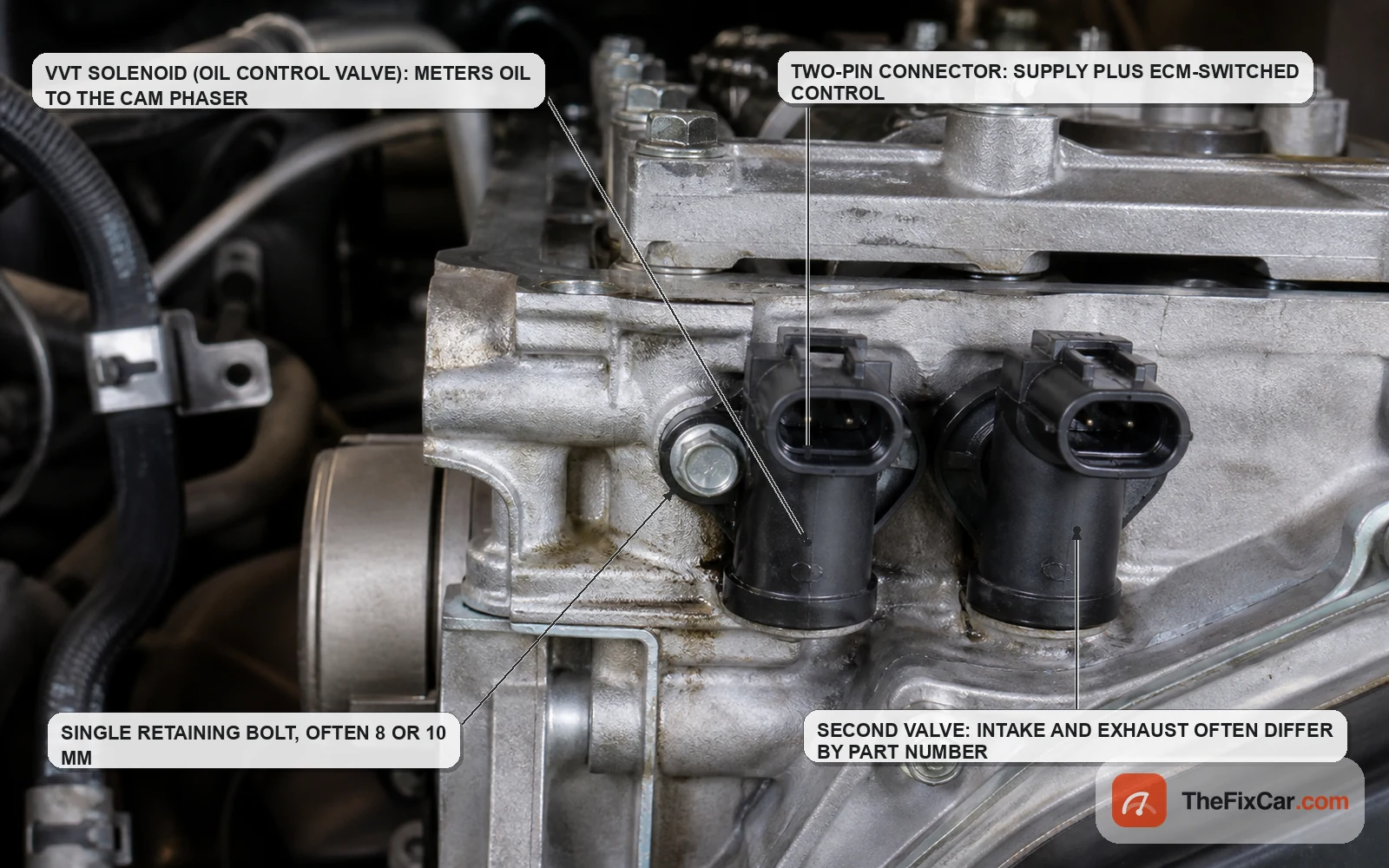
- Inline four cylinder. Typically one or two valves at the front of the head, on the timing cover end. Dual-phasing engines have separate intake and exhaust valves side by side.
- V6 and V8. Many dual overhead cam engines use one valve per camshaft, so two or four in total, often mounted in the front covers rather than in the heads. Cam-in-block engines and some manufacturer-specific layouts use fewer, or put the valve in a cover, the block, the oil pump, or a separate housing. Bank 1 and bank 2 identification comes from the service information, not from which side looks like the front.
- Some engines put the valve elsewhere. A few designs mount the oil control valve to the oil pump or the block. General Motors’ bulletin for the 1.2L turbo engine, for example, has the technician clear debris from the OCV mounting hole while the oil pump is out[4], which tells you the valve is nowhere near the valve cover on that engine.
- Cam-in-block and rocker-arm systems. Honda’s rocker arm oil control valve sits at the front of the head and feeds the rocker assembly rather than a sprocket-mounted phaser[5].
Look up your engine before you start removing covers. Vehicle-specific location, bolt size, and torque belong to the service information for your exact year, engine, and trim, and guessing wastes more time than looking it up.
Before you condemn the solenoid
For a performance, correlation, or response complaint, make these checks before replacing the valve.
- Oil level and condition. Low, filthy, thickened by additives, or the wrong viscosity all interfere with a hydraulic phasing system. Subaru’s chart has the technician correct the level or change the oil and filter, then re-evaluate, before moving on[2]. If you are unsure what your engine takes, our page on reading an engine oil specification and matching viscosity to the manual covers it, and how to check engine oil properly, cold and hot covers the measurement.
- Mechanical cam timing. A stretched chain, a worn guide, or a jumped tooth produces correlation codes that look electrical from the driver’s seat. Volkswagen’s procedure is explicit: check valve timing, adjust it if it is wrong, and only replace the control valve if the timing is correct[3].
- Oil pressure and the feed screens. Phasers need real pressure and clean oil to move. If the strainer or the small VVT filter screens are loaded with debris, a new valve will not fix the complaint[2].
- Freeze frame and live data. Note the coolant temperature, load, and rpm at which the code set. A fault that only appears hot at low idle points somewhere different than one that sets on a cold start.
Do not swap the intake and exhaust solenoids to test them unless you have confirmed the two carry the same part number. On plenty of engines they look identical and are not: different flow rates, different default positions, different calibrations. A swap test with mismatched valves can create a fault that was not there.
Visual inspection
- Let the engine cool. You will be near hot metal and opening an oil passage.
- Look at the valve body where it meets the head. Oil weeping at that joint suggests a hardened seal, though a leak from a valve cover gasket above can run down and imitate it.
- Check the exposed portion of the solenoid for impact damage, a cracked plastic body, or a bent mounting flange.
- Follow the harness from the connector back as far as access allows. Look for chafing where it crosses a bracket, heat damage near the exhaust side, and any repair splice from previous work.
- Note anything unusual in the oil filler neck: heavy varnish, sludge, or a milky film all change what you should suspect.
Connector and circuit inspection
This is where plenty of VVT faults live, and it costs nothing to check. General Motors’ procedure for a related oil control solenoid opens by removing the connector and inspecting for proper terminal tension, crimps, and locks[4]. Those three words cover a lot of connector failures.

- Disconnect the connector with the key off. Release the lock rather than pulling on the wires.
- Inspect both halves for green or white corrosion, pushed-back or spread terminals, and melted plastic.
- Check terminal tension with a matching male terminal or a proper tension tool. A terminal that accepts the pin with no drag can pass a static resistance test and still drop out under vibration.
- Look for oil inside the connector. Oil inside a VVT connector strongly suggests oil intrusion, either past an internal valve seal or from a leak path above it, so trace where it came from before calling the valve failed. On the models it covers, Subaru’s bulletin calls for replacing the affected valve, and replacing the harness if cleaning the contaminated wiring does not work[2].
- Check the wiring between the solenoid connector and the control module for excess resistance. Subaru’s chart flags a reading above 1 ohm on that circuit as a problem to repair[2]. Confirm the acceptable figure for your vehicle, since circuit length and specification vary.
- Wiggle-test while watching the reading. Manipulating the harness while monitoring resistance is exactly how GM has technicians isolate an intermittent[4].
Resistance test
A digital multimeter set to ohms measures the coil winding and nothing else. Measure with the circuit de-energized and the solenoid disconnected, since a meter’s own test current cannot give a valid reading on a live circuit[7].
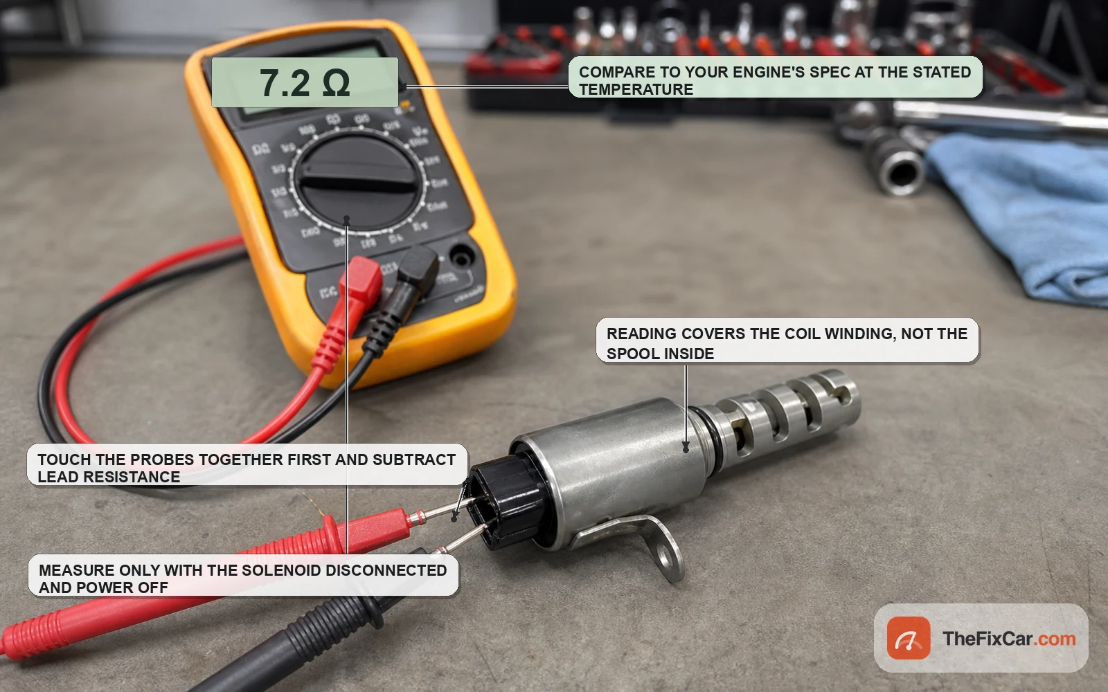
- Key off. Disconnect the solenoid connector.
- Put the meter on the ohms range and touch the leads together first. Note the lead resistance and subtract it from your measurement, because on a single-digit specification a tenth of an ohm of lead resistance matters.
- Measure across the solenoid’s two terminals.
- Compare to the specification in the service information for your engine, at the stated temperature. Published figures vary widely by design. GM specifies 10 to 30 ohms for one oil pressure control solenoid on its 1.2L turbo engine[4], though that is an application-specific figure for that solenoid rather than a VVT solenoid specification you can carry over. Take your number from the service information for your engine, never from another one.
- Interpret carefully. An overrange or open-circuit reading, or a near-zero reading, points strongly at a fault in the coil or the terminal path. Confirm the meter setup, the lead contact, the terminals, the temperature, and the specification before calling the solenoid failed. A reading somewhat outside spec is a reason to look harder, not automatic proof, since coil resistance rises as the winding heats and specs are quoted at a reference temperature.
A coil that measures in spec cold can still break down when hot, and a perfectly good coil tells you nothing about whether the spool it drives is free to move. ASE’s own certification material separates powertrain mechanical problems from electrical and electronic ones in VVT and variable valve lift systems for exactly this reason[1].
Power and control signal test
On the typical two-wire hydraulic OCV, one terminal receives a supply and the control module switches the other, varying the duty cycle to position the spool. Verify the wiring layout for your engine before probing, because supply-side and ground-side switching are both used.
- Reconnect the solenoid and back-probe the connector so the circuit stays intact. Piercing insulation invites corrosion later.
- If the wiring diagram and test procedure say supply voltage should be present with the key on and the engine off, verify it at the feed terminal against a known good ground. If they do not, run the voltage test under the conditions that procedure specifies, since some systems power the circuit only once enable conditions are met.
- Start the engine and let it reach operating temperature. Many systems require specific oil temperature, rpm, and load conditions before meaningful cam phasing is commanded.
- Switch the meter to its duty cycle function, or use a scope, and watch the control terminal while an assistant raises and lowers engine speed. Where the service procedure says the system should be actively commanding phasing, the duty cycle or control waveform should change as the commanded cam position changes. A flat signal at 0 or 100 percent with no response points first at enable criteria, the module command, driver protection, or wiring, though a shorted or incorrect solenoid can also pull the circuit out of range.
- Check the voltage drop on the ground side under command. A drop beyond the limit given in the service information suggests a poor ground or a corroded terminal.
Do not ground the control wire by hand to force the valve on. On some systems that bypasses a driver the module monitors, and it can set additional codes or damage the driver.
Bench activation test
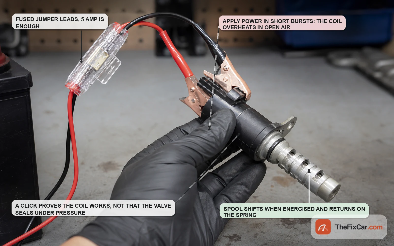
With the solenoid out, a fused jumper tells you whether the armature moves at all.
- Clean the outside of the valve so nothing falls into the port when you handle it.
- If the service information allows direct battery-voltage activation, wire a fused jumper from battery positive to one terminal and from the other terminal to battery negative, using the specified fuse rating or a low-amperage inline fuse suited to the circuit. Use the terminal polarity and the test procedure specified for that valve. Do not assume every two-wire VVT solenoid can be powered straight from the battery.
- Apply power in short bursts and watch the spool at the tip of the valve. It should shift briskly and return under spring pressure when you break the circuit.
- Keep each burst brief. The coil is designed to run on a duty-cycled command with oil around it, not continuous current in open air. If the service information gives a maximum energizing time, respect it.
- Repeat several times. A spool that moves once and then hesitates on a later cycle is telling you more than a single clean stroke.
What this test does not settle: a valve can click on the bench and still fail in service. Under running oil pressure the spool sees hydraulic force it never sees in your hand, and internal leakage past a worn spool does not announce itself with a click. Treat a bench click as evidence the electrical half works, nothing more.
Scan-tool activation test
Commanding the valve on the running engine is the most controlled way to exercise the whole chain: module, wiring, solenoid, oil supply, and phaser together. ASE’s task list for advanced engine performance includes performing active tests of actuators with a scan tool to determine needed action[1].
- Bring the engine to full operating temperature with the oil level correct.
- Open the scan tool’s bidirectional controls and find the VVT or cam actuator output test. Not every tool or vehicle supports it, and some manufacturers gate it behind their own software.
- Command the actuator while watching the cam angle or camshaft position deviation parameter, plus rpm.
- On a test that directly commands phaser movement, a healthy system moves actual cam angle toward the commanded value, or meets whatever response criteria the service procedure gives. Idle may or may not change audibly, depending on the test and the engine’s control strategy. No movement with the command applied shifts suspicion toward the valve, the oil supply, the phaser, or a circuit fault that only shows up under load, even where the earlier wiring checks passed.
- If bidirectional control is unavailable, log desired versus actual cam position during a road test instead. That data is useful but less controlled than a commanded test, and a persistent gap between the two is worth following up.
Clues that shift suspicion
None of these separates faults with certainty. They change the odds, which is all a clue is meant to do.
| What you find | Leans toward | Still possible |
|---|---|---|
| Coil open or shorted | Failed solenoid, electrical | A damaged terminal reading as an open |
| Coil in spec, no response to command | Stuck spool, plugged screen, low oil pressure | Module driver fault |
| Oil inside the connector | Failed valve seal | Oil tracking down from a leaking cover above |
| Fault clears after an oil and filter change | Contamination or wrong viscosity | An intermittent that has not returned yet |
| Correlation code with a smooth-running engine | Sensor, reluctor, or wiring | Early chain stretch |
| Rattle for a second or two at cold start | Phaser or chain tensioner | Accessory drive or exhaust heat shield noise |
When cleaning makes sense
Cleaning is worth attempting when the evidence points at deposits rather than damage.
- The coil measures within specification and the connector is dry and undamaged.
- The valve is visibly varnished or gritty, and the vehicle has a history of long oil intervals.
- The screen on the valve, where one is fitted, is dark with sludge but intact.
- The spool moves on the bench but hesitates or sticks on repeated cycles.
- You are pairing the cleaning with an oil and filter change, so the valve is not immediately recontaminated.
When cleaning is a waste of time
- The coil is out of specification, open, or shorted. No solvent repairs a winding.
- Oil is in the electrical connector. Treat that as strong evidence of oil intrusion or a failed seal, then verify the leak path. Subaru’s answer on the vehicles its bulletin covers is a new valve[2].
- The spool or bore is scored. Wear changes internal leakage, and leakage is what a phaser cannot tolerate.
- The sealing groove is damaged or out of specification. Honda’s bulletin for leaking rocker arm oil control valves names a deteriorated gasket or a gasket groove out of specification and calls for replacing the valve, not reworking it[5].
- Mechanical cam timing is wrong. Fix the timing first[3].
- The valve is integral to another assembly. Where the OCV is built into an oil pump or a housing, cleaning it in place risks pushing debris into the passage rather than out of it.
- The engine has heavy sludge. Where VVT strainers or filter screens are fitted, contamination can return quickly unless the oil supply path is cleaned according to the service information[2].
Cleaning procedure
Cleaning solvents and methods are one of the areas where OEM guidance differs, so check the service information for your engine before you start. The bulletins cited here direct technicians to replace a contaminated valve rather than clean it, so confirm that cleaning is an option for your application at all.
- Work with the valve on the bench, never on the engine, so debris cannot fall into the oil gallery.
- Keep solvent away from the electrical end. Spraying into the connector or soaking the coil body can damage the winding insulation and the internal seal.
- Flush the hydraulic end only with a cleaner approved by the service procedure for that valve. If no cleaning procedure or solvent is specified, replacement is safer than experimenting with aggressive solvents. Where an approved aerosol cleaner is specified, direct it through the hydraulic ports. Catch the runoff and look at what comes out: metallic glitter is a reason to stop and investigate the engine rather than reinstall the valve.
- Remove deposits with a lint-free cloth, which is what GM specifies for debris around the OCV mounting area[4]. If you reach for a brush, use only one soft enough that it cannot scratch the valve or the bore. No wire brushes, no abrasive pads, no picks against the sealing surfaces.
- If a removable screen is fitted and the service information says it can be serviced separately, clean it from the clean side outward so debris exits the way it came in.
- If the service information allows energizing the valve during cleaning, cycle it only after excess solvent has drained and the vapors have cleared, then flush again as directed.
- Let the valve drain and dry as the service procedure specifies. Use compressed air only where the manufacturer permits it, and never direct high pressure at the spool, the screen, or the seals. Lubricate the seals, and any hydraulic surfaces the service procedure identifies, with clean engine oil of the specified viscosity before installation.
Set your expectations honestly. Cleaning helps a varnished valve and does nothing for a worn one. Scoring, visible wear, or a service limit sometimes separates the two before the valve goes back on; where nothing measurable shows up, how the valve behaves afterward is the test.
Removal
- Park on level ground, let the engine cool, and disconnect the negative battery terminal if the connector is close to anything you might short.
- Remove whatever blocks access: engine cover, intake tube, coolant hose, occasionally the alternator or a bracket. Support anything you unbolt rather than letting it hang on its wiring.
- Release the connector lock and unplug the solenoid.
- Clean the area around the valve before loosening it. Anything sitting on the head goes into the oil passage the moment the valve comes out.
- Remove the retaining bolt with the correct socket for your application. Keep it separate, since these are often a specific length.
- Pull the valve straight out with a gentle twist. Do not lever against the head or housing with a screwdriver: the flange breaks and the sealing surface marks easily. If it resists, twist rather than pull harder.
- Expect a small amount of oil. Have a rag under the port and plug the opening with a clean lint-free plug while the valve is out.
- Inspect what came out. Note the condition of the tip, the seal, and any screen, and compare the old part to the new one before you fit anything.
O-ring and seal replacement
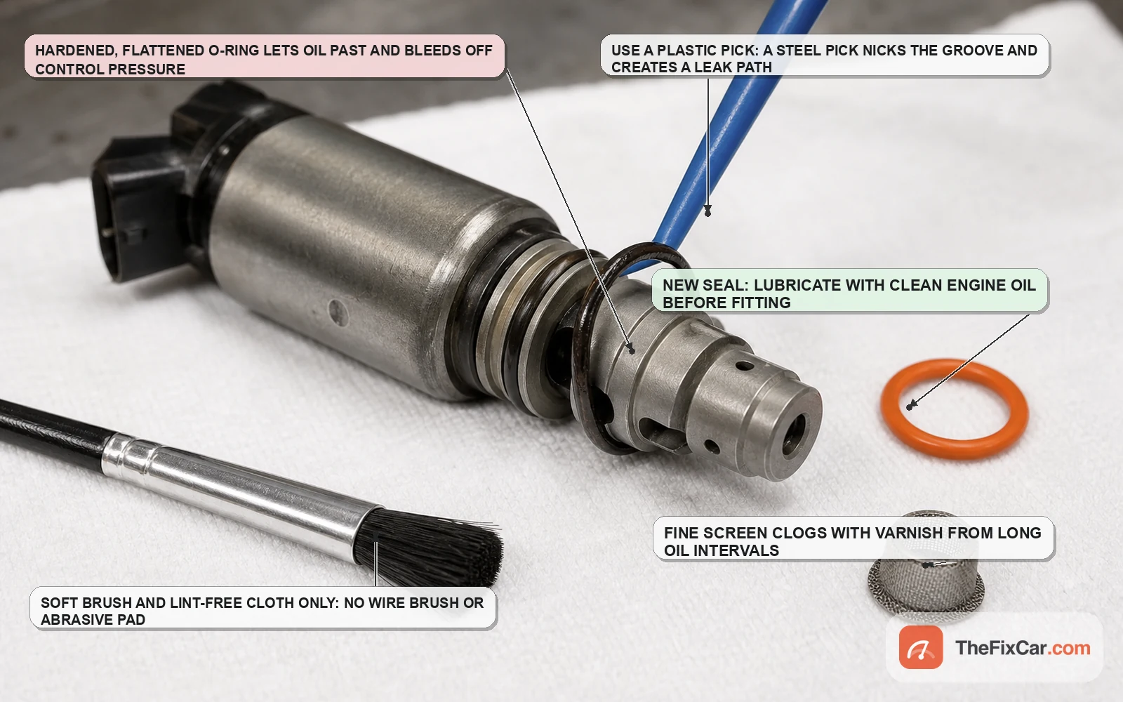
Separate the seals by what each one does. The body O-ring seals the valve to the head or housing, and a hardened one shows up as an external oil leak at the flange. Oil inside the connector points instead to intrusion through the valve’s internal sealing path, or to a leak above that has tracked down. Internal leakage that spoils phaser control is a third, separate fault inside the valve or the oil circuit.
- Most replacement solenoids arrive with new seals fitted. Confirm they are the correct ones for your application rather than assuming.
- Remove the old O-ring with a plastic pick. A steel pick that nicks the groove can create a leak path a new seal will not close.
- Inspect the groove and the sealing bore in the head or housing. If the groove is damaged or out of specification, replace the valve. Honda’s bulletin treats an out-of-specification gasket groove as grounds for a new valve on the models it covers[5].
- Match the new seal by size and material to the original. Do not substitute a generic hardware-store O-ring: material choice governs how the seal handles hot oil.
- Lubricate the seal with clean engine oil. Grease is not a substitute unless the service information calls for it, and silicone sealant does not belong here at all.
- Roll the seal into the groove without stretching it more than necessary, and confirm it is seated evenly all the way round.
Installation
- Wipe the bore in the head, cover, or housing with a lint-free cloth and remove the plug you fitted earlier.
- Insert the valve straight, without rotating it hard against the bore. A cocked entry can roll the O-ring out of its groove, which shows up as a leak once the engine has run.
- Start the retaining bolt by hand, then torque it to the figure in the service information. These bolts are typically low torque into aluminium, so overtightening strips the threads and undertightening lets the valve lift and leak.
- Reconnect the connector until the lock clicks. Check that the seal on the connector body is present and seated.
- Reinstall everything you removed for access, then reconnect the battery.
- Check the oil level. If the engine lost more than a trace during removal, top up to specification before starting.
What to do after replacement
- Change the oil and filter if contamination was part of the picture. Use the specified viscosity and skip aftermarket additives. Subaru’s bulletin is blunt on both points[2], and Volkswagen’s procedure ends with an oil and filter change after replacing the control valve[3].
- Record the freeze frame data first, then clear the stored codes with a scan tool rather than by disconnecting the battery. Clearing codes commonly resets the readiness monitors, so expect to complete a drive cycle afterward.
- Start the engine and listen carefully. Follow any manufacturer-specific priming procedure for the system you worked on. Do not assume that a new noise from the timing area is normal. If it persists, gets worse, or arrives with an oil pressure warning, shut the engine off and investigate before driving.
- Check for leaks at the valve flange with the engine warm, then again after it has sat overnight.
- Perform any relearn the manufacturer requires. Some engines want an idle relearn or a cam position learn after VVT work. Whether your vehicle needs one, and how it is performed, comes from the service information for your model.
- Watch live data. With the engine at operating temperature, desired and actual cam angle should track closely. A gap that remains after the repair points away from the valve you just fitted, toward the phaser, the chain, oil supply, the cam and crank reference signals, wiring, the module command, an incorrect part number, or a relearn that has not been done.
- Complete a drive cycle so the relevant monitors run, then recheck for pending codes before you call the job finished. If the light comes back, our page on what a flashing check engine light means and when to stop driving covers the difference between a steady and a flashing lamp.
If the original complaint survives a correctly fitted valve, widen the search rather than fitting a second one: the phaser, the chain, oil pressure, the cam and crank reference signals, the wiring and module command, the part number you fitted, and any relearn the vehicle requires. Our companion article on bad VVT solenoid symptoms and the faults that imitate them covers the symptom side in more depth.
DIY or shop
- DIY difficulty: Easy to Hard, and it depends entirely on where the valve sits. A front-mounted valve on an accessible engine can be a single bolt. A rear bank valve on a transverse V6, or a valve integrated with the oil pump, is a different job. On accessible valves the diagnosis is often the harder half of the job.
- DIY cost: Roughly $30 to $200 for the part depending on brand and engine, plus a multimeter and a basic socket set. A scan tool with bidirectional control and live data is what actually shortens the job.
- Shop cost: Roughly $300 to $600 for many conventional, accessible VVT solenoids. Integrated assemblies and difficult-access applications can exceed $1,000. Diagnosis may be billed separately.
Cost figures here are rough U.S. estimates. Warranty coverage, model, part brand, and local labor rates move the price in either direction.
FAQ
Can you drive with a bad VVT solenoid? It depends on what failed and how the engine behaves. If a confirmed electrical solenoid fault is the only problem and the engine runs normally, a short trip to a repair facility may be reasonable. If the code is a cam to crank correlation code, or the engine misfires, has lost noticeable power, makes noise from the timing area, or shows low oil pressure, stop driving and diagnose. A cam timing fault that is actually a chain or phaser problem can get much more expensive with miles.
Will cleaning a VVT solenoid fix a P0011 code? Sometimes, and only when deposits are the cause. Cleaning does nothing for a failed coil, a scored spool, a bad phaser, or stretched timing. Because a P0011 names an over-advanced or performance condition and not a component, treat cleaning as one candidate repair rather than the answer.
How do I know if it is the VVT solenoid or the phaser? No single check separates them cleanly. If the coil is in spec, the wiring is good, and the valve responds to a commanded test while the cam angle refuses to follow, suspicion shifts toward the phaser, the oil supply, or the chain. Manufacturers have documented cold-start noise traced to the phaser rather than the valve[6].
What resistance should a VVT solenoid read? Whatever the service information for your engine specifies at the stated temperature. Published values differ by design. GM specifies 10 to 30 ohms for the oil pressure control solenoid on one of its turbo engines[4]. A number borrowed from another vehicle is worse than no number.
Do I need to replace the VVT solenoid in pairs? Not as a rule. Intake and exhaust valves on the same engine often carry different part numbers and different calibrations, so replace what tests bad and verify part numbers before assuming the two are interchangeable.
Can a bad VVT solenoid cause an oil leak? Yes, though the leak paths are worth separating: a hardened body seal leaks externally at the valve, while oil inside the connector points to intrusion through the valve or oil tracking from another leak. Honda documented deteriorated gaskets and out-of-specification gasket grooves on a specific rocker arm oil control valve as a cause of leaks[5].
Does thicker oil help a noisy VVT system? It is a bad idea on a phasing system. The valve and the phaser are sized around a specified viscosity, and Subaru’s guidance is to use the specified viscosity and avoid supplementing the oil with additives[2].
Related maintenance guides
- Bad VVT solenoid symptoms and the faults that imitate them
- Oil light flickers at idle but the oil level is full: what to check
- Engine oil specification: how to read the grade your engine actually needs
- How to check engine oil properly, cold and hot
- Rough idle when cold: what changes as the engine warms up and why
- How often to replace spark plugs and what worn plugs feel like