A wheel speed code does not prove the sensor failed. One manufacturer opened a service bulletin because an abnormally high number of hub bearing assemblies were being returned under warranty for wheel speed faults while testing as functional, and announced that returned assemblies would be tested and bad claims rejected.[2]
The fault often sits in the gap the sensor reads across, the harness carrying the signal, or the ring it is pointed at. Prove the signal path before the parts counter does.
This is the order that finds the fault in an order that keeps you from guessing: work out which type of sensor you have, test the circuit the way that type demands, decide whether cleaning can help, and only then remove parts. Published values for the tests below are collected separately in our ABS wheel speed sensor specifications, with the document each one came from.
Quick answer
On a vehicle with a separately replaceable sensor the part itself may be inexpensive. On other designs the sensor or the encoder is tied to the hub or bearing assembly, and both the time and the bill depend far more on that and on corrosion than on the code you read. Testing needs a multimeter at minimum, and an oscilloscope or a scan tool with live wheel speed data if you want to catch the intermittent ones. The step nobody should skip is identifying passive or active before touching a meter, because the wrong test on an active sensor produces a number that looks like a diagnosis and is not one.
Why it matters
A wheel speed signal is not only an ABS input. Depending on the vehicle, stability control, traction control, hill hold and sometimes the speedometer or transmission strategy read the same wheel sensors. A sensor reporting nonsense can make the car intervene when it should not, which is worse than an ABS light.
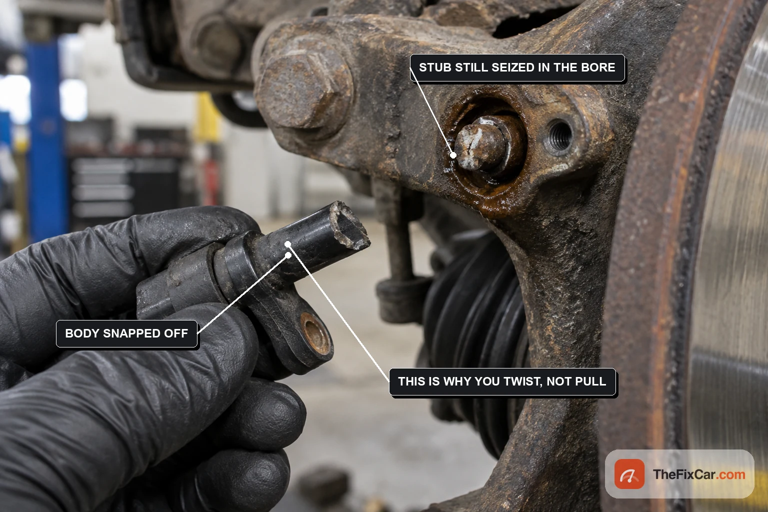
The other reason to be careful: on the common design the sensor sits in a bore in the knuckle or hub carrier, held there by corrosion, and it snaps off if you rush it. A quick job becomes a hub carrier removal.
When to test the wheel speed circuit
- ABS light with a wheel-specific code. The code names a circuit and a wheel, not a part.
- Warning only above a certain speed. Points at the ring, the air gap or an intermittent connection rather than a dead sensor.
- Speedometer dropping to zero while moving. On cars that take vehicle speed from a wheel sensor.
- ABS activating on dry road at low speed. One wheel reporting a speed the others disagree with.
- Fault that comes back with road surface rather than speed. Suggests the harness or connector.
Step one: work out which sensor you have
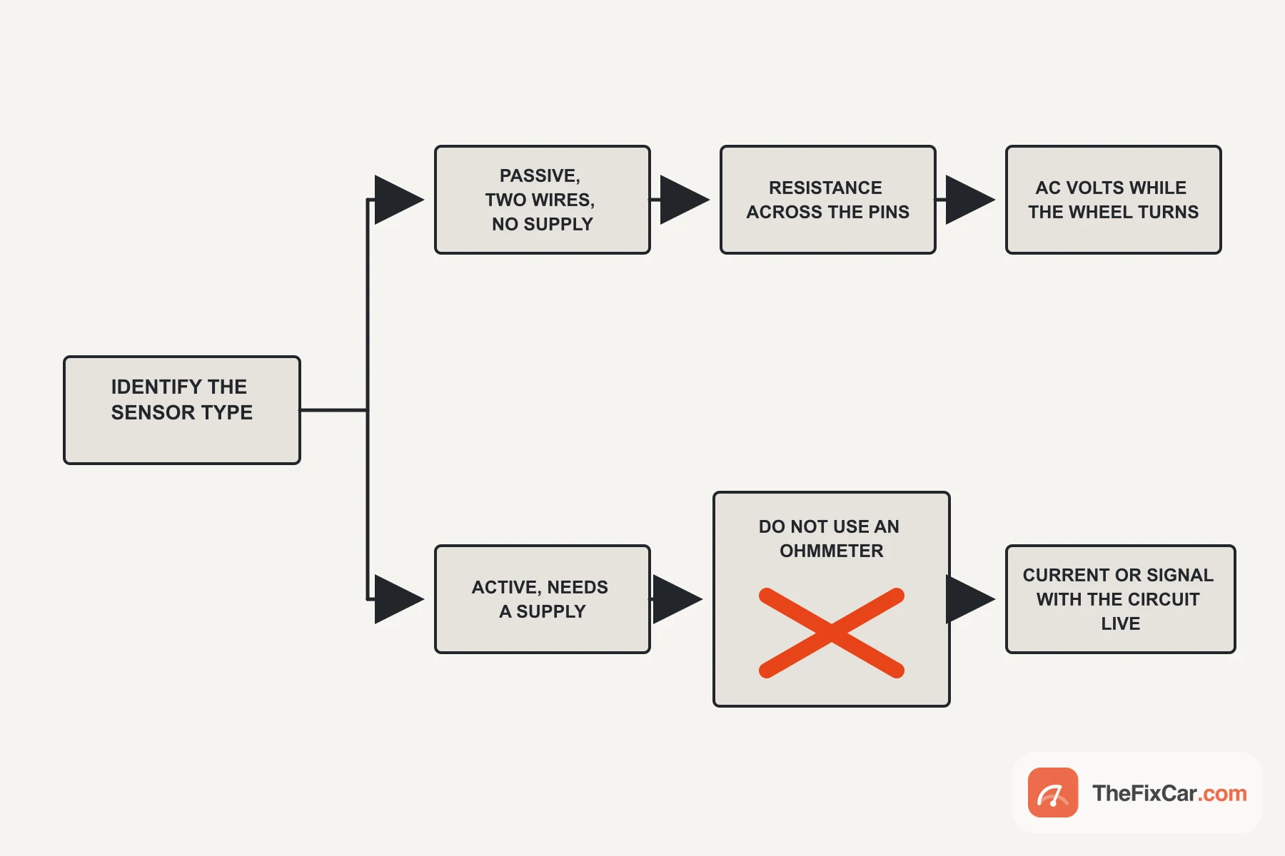
Everything downstream depends on this, and the answer is in the wiring diagram rather than in the connector. A passive sensor is a coil with two wires and no supply. An active sensor is powered, and the module feeds it before it will say anything at all.
Look up the circuit for that wheel. A supply feed in the diagram means active, and that decides which of the two test paths below applies. It says nothing about the sensor’s condition, and measuring voltage at the connector is not a reliable substitute, because bias voltage and backfeed put voltage on passive circuits too.
Testing a passive sensor
Two measurements, and they answer different questions.
Test: resistance across the sensor pins with the sensor unplugged. Expected: the figure for your vehicle. What it proves: the winding is not open or shorted at rest. What it does not prove: that the sensor produces a usable signal. Leave the sensor plugged in and you measure it in parallel with the module, so the number is not the sensor’s.
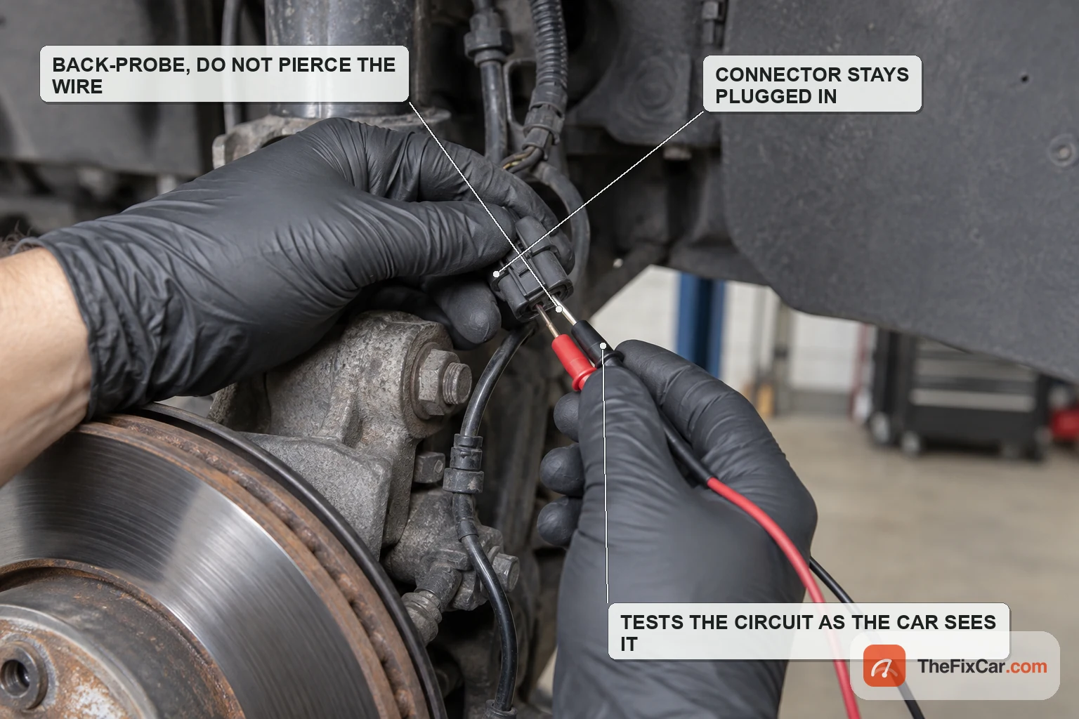
The second measurement makes the sensor work. With the meter on AC volts at the module end, an assistant turns the wheel steadily by hand: the Bendix checklist, for its own sensor, wants 0.25 volts AC at half a revolution per second.[1] A reading there tells you the sensor generates and the harness carries what it generates. It does not tell you the signal survives at road speed or over bumps.
Temperature matters for the resistance figure, because copper climbs with heat. The same checklist puts a 0 to 100 °F window on the measurement and tells the technician not to take it on a hot wheel end.[1]
Testing an active sensor
An ohmmeter does not give a universal health check for an active sensor, and published guidance advises against resistance testing some active designs at all.[4] The test needs the circuit powered, and the exact method belongs to the vehicle. The MV-1 bulletin, for example, has the technician run a fused jumper from the battery and read current in the sensor circuit while the wheel turns slowly, and that procedure is written for those vehicles rather than as a universal method.[2]
Test: current or signal with the circuit live, by the method your service information gives. Expected: whatever pattern that vehicle’s procedure describes, commonly a two-level switch whose rate follows wheel speed. Signal formats differ between designs. What it proves: the sensor is switching. Whether the module receives it is only proven by measuring at the module end or by watching live data. What it does not prove: that it will keep doing so warm, wet, or under suspension load.
Whichever type you have, compare the four channels
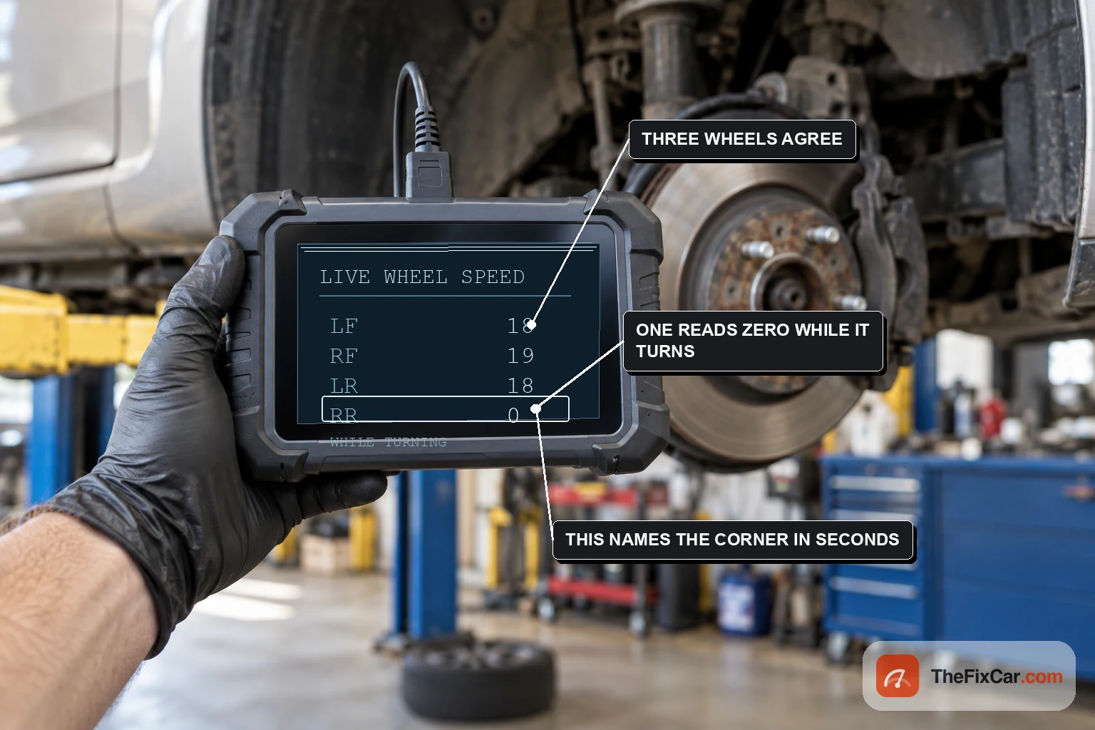
A scan tool comparing all four wheel speed channels works the same on either sensor type, and it is usually the fastest way in. The manufacturer’s road test is where that comparison belongs: the MV-1 bulletin has the technician drive above 15 kph and watch the data during deceleration.[2] Where a stationary test is permitted instead, the suspect wheel is raised and turned by hand.
A wheel that drops to zero or behaves unlike the other three has identified the corner to investigate. It has not proven the sensor is bad.
Do not simply lift all four corners and spin things. On all wheel drive, four wheel drive, hybrid and electric vehicles, turning one wheel can drive the others through the drivetrain, and several of those vehicles have their own procedure for supporting and rotating wheels. Look it up before the car leaves the ground.
Finding the intermittent ones
The faults that cost the most time are the ones that pass every static test. A connector can pass a continuity check standing still and separate the moment the suspension moves.
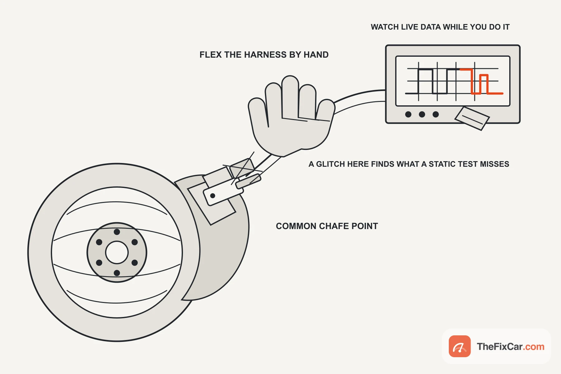
These need two different approaches, and mixing them puts your hands near a turning wheel for no reason.
For a suspected wiring fault, disconnect the circuit the way the wiring procedure requires, then watch continuity while flexing the harness along its length and working the connector.[3] A reading that breaks as your hand moves has located the fault to that section.
For a signal dropout that only appears in use, record live data or capture the waveform while the wheel is rotated under the test procedure the manufacturer specifies. A clean result either way does not rule out a fault under load, because suspension travel and heat reach places your hand does not.
Check the obvious chafe points while you are there: where the harness passes the strut bracket, where it enters the wheel arch liner, and anywhere a previous repair left a cable tie in the wrong place.
Cleaning: when it is worth doing
Cleaning only helps when contamination or incorrect seating is affecting the signal. What you clean depends on what the car uses.
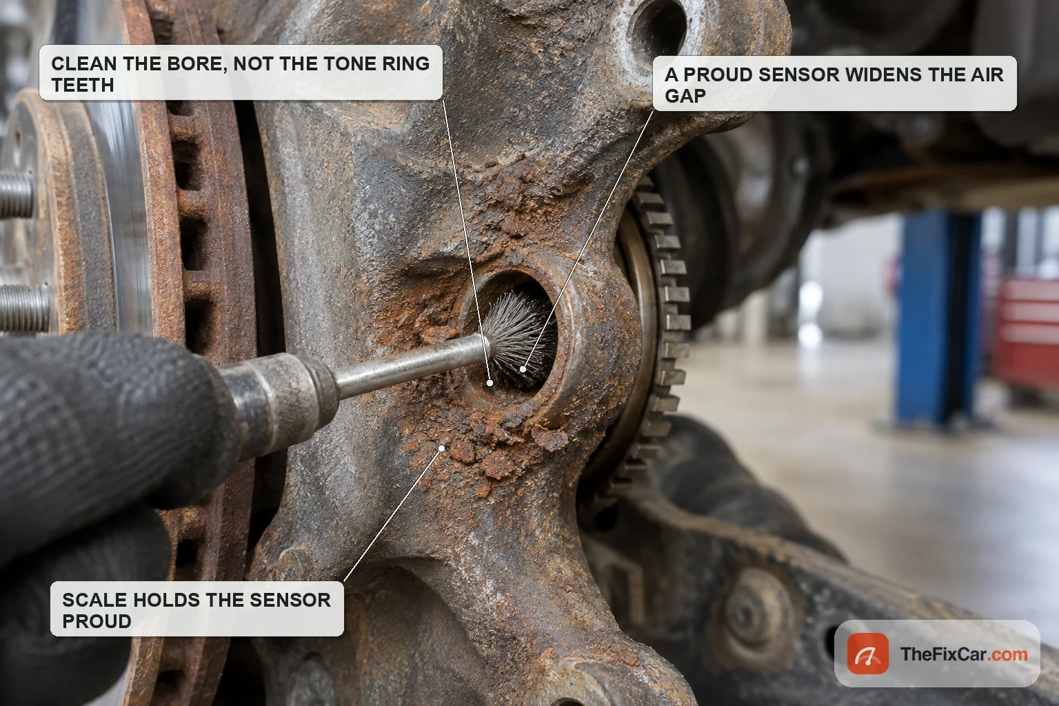
Worth doing: a magnetic sensor tip matted with steel filings, which sits in the space the sensor reads across, and a bore packed with rust scale, which holds the sensor out and widens that gap. Neither is a broken part.
Not worth doing: cleaning the sensor tip or the bore will not help a tone ring with a damaged tooth or a sensor that fails its electrical test. A corroded connector is a separate job with its own contact cleaner and its own inspection, not something the sensor end fixes.
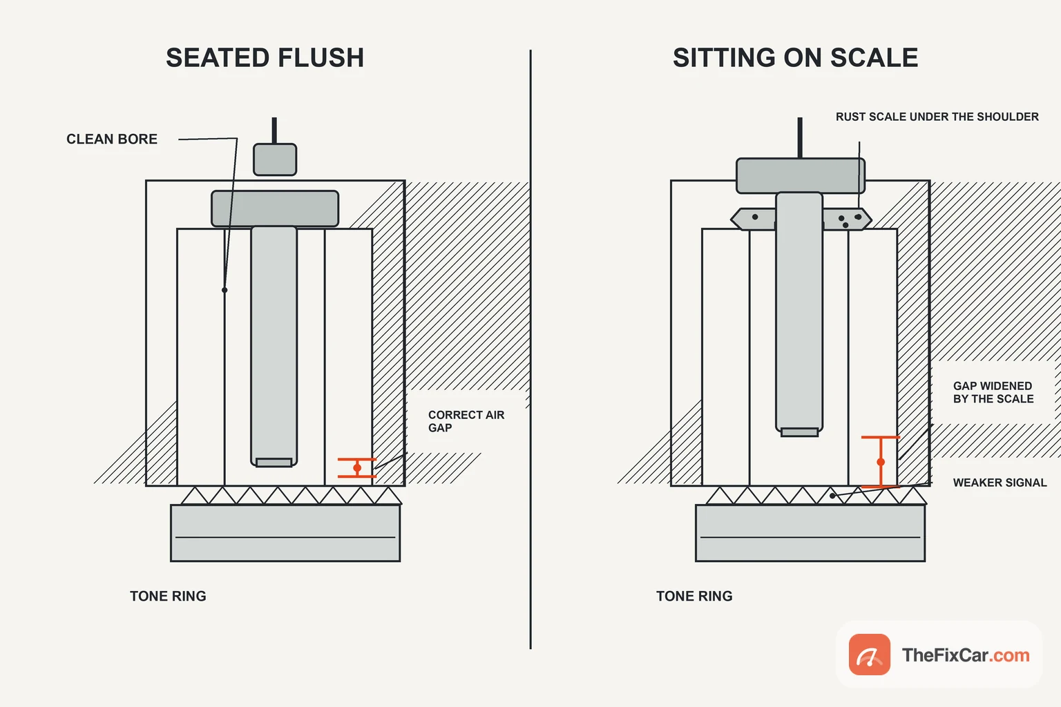
Wipe the sensor tip with a clean rag or a plastic scraper. Do not use steel wool: it sheds fibres onto the one surface designed to attract and hold them.
Where the service information allows it, the bore can be cleaned with a small wire brush so the sensor seats. Check what the housing is made of first: a wire brush in a soft aluminium bore removes more than the scale.
A magnetic encoder ring is a different object and needs a different hand. GM describes it as a magnetized nitrile rubber ring, usually brown, carrying north and south pole pairs around its circumference, built into the inboard side of the bearing hub assembly.[5] Ferrous debris sticking to it produces the same wheel speed codes a failed sensor would, and GM states that in most cases those codes can be repaired by cleaning that debris off rather than replacing anything.[5]
Their procedure is a dry soft nylon bristle brush used gently, then a mild soap detergent and wipe dry if debris remains, taking care not to damage the bearing outer seal. They also warn against using any magnetic tool to lift the debris, for the obvious reason.[5]
Do not treat a magnetic encoder ring like a toothed reluctor. A toothed steel ring will usually take a soft brush if the service information permits it, which is the opposite of what an encoder wants. On the GM design described in that bulletin the encoder is a magnetized nitrile rubber ring, typically brown, built into the bearing hub.[5] Other designs can look different, so do not identify one by colour alone. If you cannot tell which you have, stop and check the service information before anything touches it.
First: is the sensor a separate part on your car?
Check how the sensor is serviced on that vehicle before undoing anything. The steps below apply to a separately replaceable sensor sitting in a bore in the knuckle or hub carrier.
Other arrangements exist and they are not the same. On some applications the sensor itself is integrated into the hub assembly, so there is nothing to unbolt on its own: the MV-1 bulletin is one documented example, where wheel speed faults were being answered by replacing hub bearing assemblies.[2] On others the sensor stays separately replaceable but reads a magnetic encoder built into the bearing, so the sensor can be changed while the thing it reads cannot. GM describes that arrangement on the vehicles its bulletin covers.[5] Look at the parts diagram before assuming either component is serviceable alone.
Removing a seized sensor
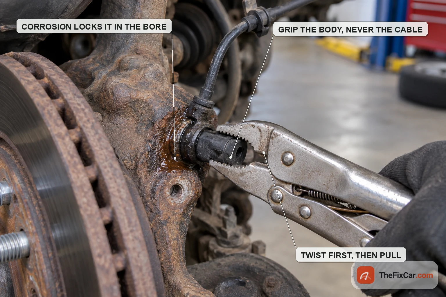
This is the part that goes wrong. Corrosion builds in the bore around the sensor body until the sensor is locked in place, and the plastic snaps when removal is forced, leaving the stub behind.
Raise the vehicle on rated stands on level ground and chock the wheels still down. A jack alone is not support.
- Unplug the connector and free the harness from its clips before touching the sensor, so nothing is pulling on the cable.
- Remove the retaining bolt if there is one, and put it somewhere you will find it.
- If the vehicle procedure allows a penetrating fluid, soak the joint and give it time. Repeat rather than force. Keep the fluid off the disc, the pads and any encoder seal: brake friction material that has been contaminated is replaced, not cleaned.
- Twist, do not pull. Grip the sensor body, not the cable, and rotate it to break the corrosion bond before you try to draw it out.
- If it still will not move, stop and check the vehicle procedure before prying, drilling or applying heat. Some sensors come out on their own, and others lead straight into hub or knuckle work.
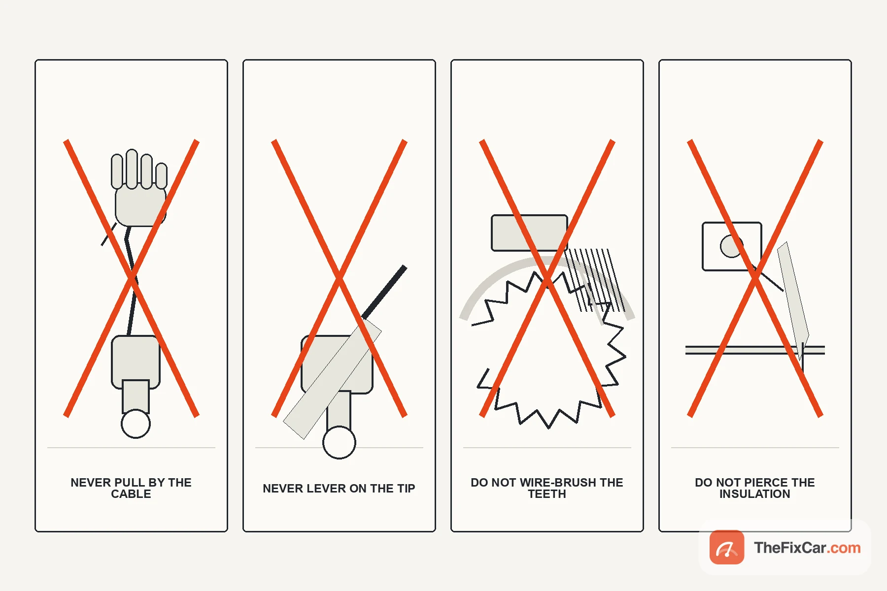
Never lever a screwdriver against the sensor tip, and never pull the sensor out by its cable. Both destroy a sensor that might have been fine, and the second one can leave you with a broken wire inside good insulation.
Fitting the new one
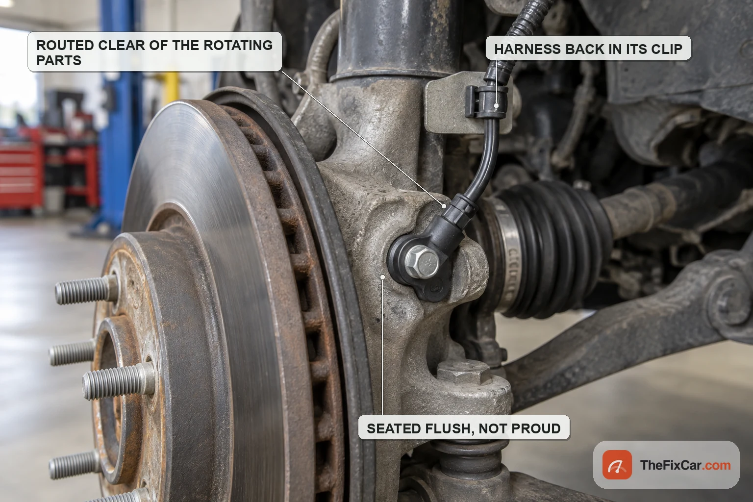
- Clean the bore first. A sensor sitting on scale is a sensor sitting proud, and a proud sensor reads across a wider gap than the designer intended.
- Check whether your service information calls for grease. Some do, some specifically do not, and the wrong grease can hold debris against a magnetic tip.
- Seat it flush and torque the bolt to the published figure. These are small fasteners in soft housings and they strip easily.
- Return the harness to every clip it came out of, following the route it originally took, clear of anything that rotates or moves through suspension travel.
- Plug in and confirm the connector is latched. A connector resting in place is the fault you will chase next month.
After replacement
Test: clear the codes, confirm everything is reconnected correctly, then drive gently in a clear area and read live wheel speeds again. Some systems complete part of their self-test only once the vehicle is moving, so follow the verification procedure for that car before treating a lamp still on at a standstill as a failed repair. Expected: on a straight road at steady speed, all four channels track closely and none drops out or spikes. Compare them against the verification criteria for that vehicle rather than against the speedometer, which is an already processed value. What it proves: the circuit works under real conditions. What it does not prove: that a second, weaker fault on another corner is not still present.
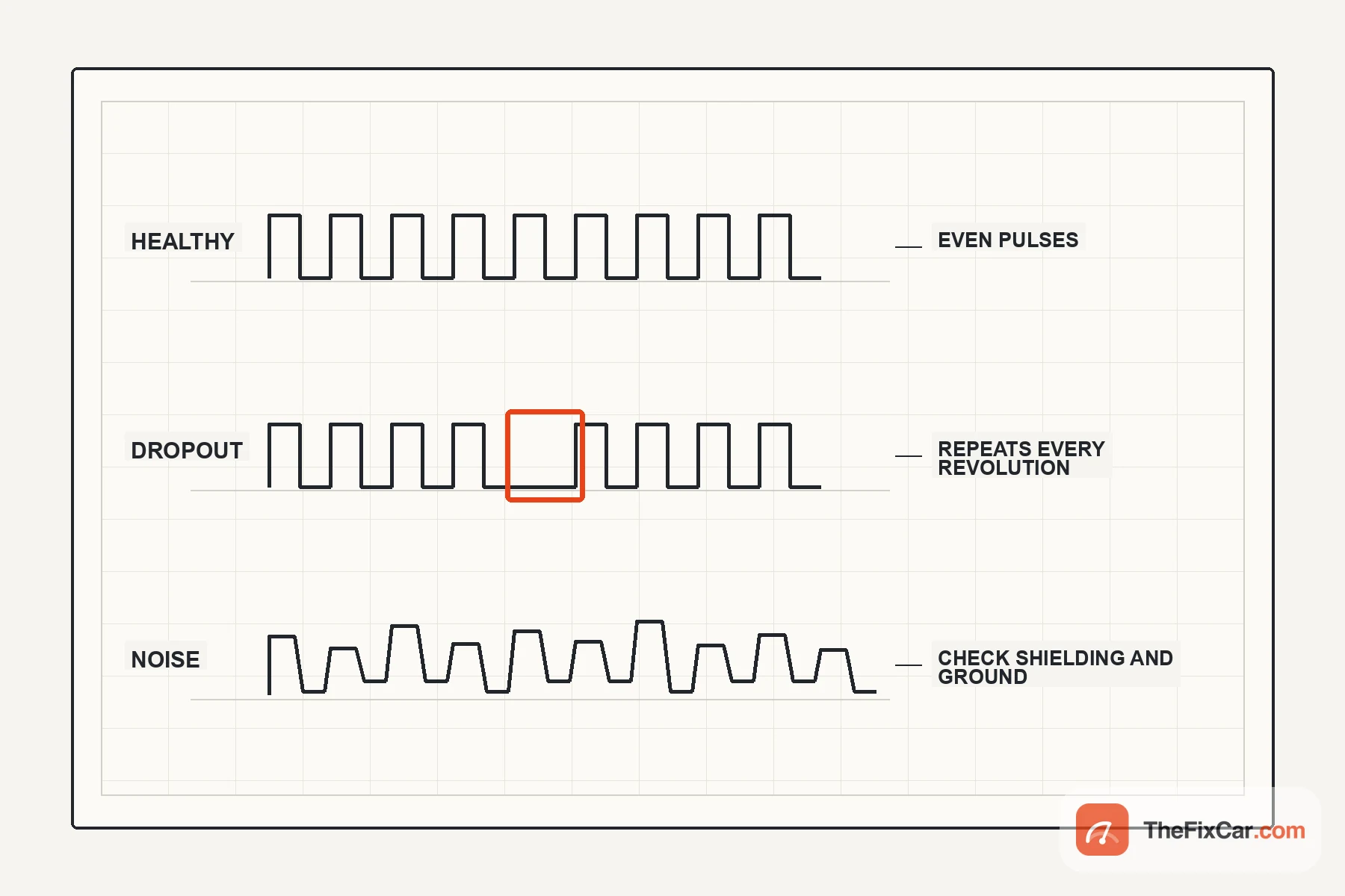
Follow the repair verification procedure for that vehicle. If the service information calls for an initialization or calibration after this work, do it before judging the result.
DIY or shop
- DIY difficulty: Moderate for an accessible bolt-in sensor. A seized one, or a design where the encoder lives in the wheel hub, turns it into a much larger repair.
- DIY cost: sensor plus penetrating fluid, and a scan tool with live data if you do not already have one.
- Part cost depends on the design. Some sensors are sold on their own. Other faults are only serviceable by replacing the hub or bearing assembly, which is a different order of money.
- Go to a shop if the sensor snaps, the code returns after replacement, or the vehicle needs a calibration you cannot perform.
FAQ
Can I test an ABS sensor with a multimeter? A passive one, yes: resistance and AC output. An active one needs the circuit powered, and an ohm reading from it is not a test of the sensor unless your service information says otherwise.
Will cleaning an ABS sensor fix it? Only where contamination is affecting the sensor tip, a magnetic encoder ring, or how the sensor seats. GM documents wheel speed codes caused by ferrous debris on the encoder that clean off without replacing anything.[5] Cleaning will not repair a damaged ring, a failed sensor or a wiring fault.
How do I get a seized ABS sensor out? Penetrating fluid, time, and twisting the body rather than pulling the cable. If it resists, look up the procedure for that vehicle before applying more force.
Do I need to reset anything after replacing one? Clear the codes and verify live data. Some vehicles also require a calibration, so check the service information rather than assuming.
Why did the light come back with a new sensor? Either the original fault was somewhere else, or the new sensor is reading the same damaged ring or sitting in the same dirty bore. Look at the tone ring, the air gap, the connector and the harness under flex.
Related brake and ABS guides
Sources & verification
Last technically reviewed: Sep 2026
Reviewed by: Tyler Brandt
Primary references: manufacturer service documents filed with NHTSA, and a published guided test for active sensor measurement
Image credit: Photographs and diagrams produced for TheFixCar. Diagrams illustrate the operating principle and are not to scale.
Suggested citation: TheFixCar, “How to Test, Clean and Replace an ABS Wheel Speed Sensor,” updated Sep 2026. https://thefixcar.com/maintenance/how-to-test-clean-replace-abs-wheel-speed-sensor/